Pulse Generator Tells Your Motors “Get Ta Steppin”

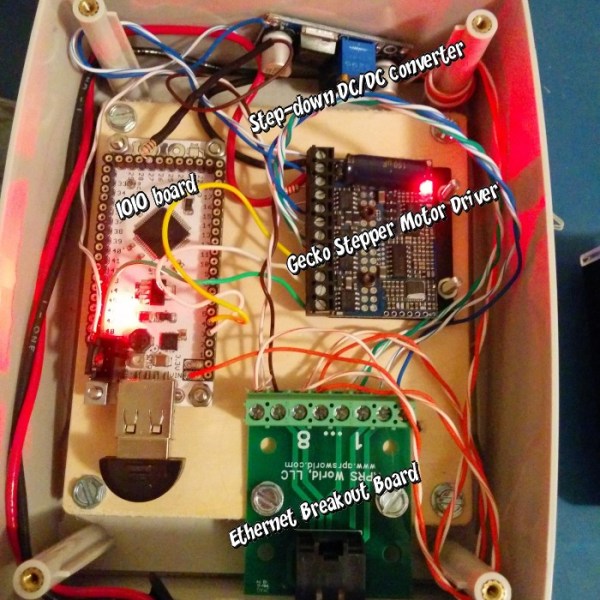
Stepper Motor Pulse Generator

Stepper motors are great for a bunch of projects; CNC machines, clocks or robots for example. Sometimes when working on a project that does include a stepper motor and driver, it would be nice to test that part of the build without hooking everything up. A pulse generator could be used to complete such a task and [CuteMinds] has put together a DIY friendly version tailored specifically for stepper motors. This device makes quick and easy work for testing out those stepper motors.

At the heart of the pulse generator is a 12F675 microchip which looks to the resistance value of a potentiometer to adjust the square wave step signal output from 20hz to 3khz. Just having the step signal would pretty cool but this project goes a little farther. There are 3 sets of headers on the board that allow you to connect either a jumper or switch in order to: 1) turn the power on, 2) enable the stepper driver and 3) select the direction the motor turns. The on-board batteries make this unit portable for remote usage.

If you are itching to make one for yourself, the Eagle schematic and board files are available for download at the above link.

Hackaday Links: June 8, 2014

hackaday-links-chain

Yes, dogfighting with RC planes is cool. You know what’s even cooler? RC jousting. Considering these eight foot long planes are probably made of foam board or Depron, they’ll probably hold up for a fairly long time. The perfect application of RC FPV.

Home automation is the next big thing, apparently, but it’s been around for much longer than iPhones and Bluetooth controllable outlets and smart thermostats. Here’s a home automation system from 1985. Monochrome CRT display panel (with an awesome infrared touch screen setup), a rat’s nest of wiring, and a floor plan drawn in ASCII characters. It’s also Y2K compliant.

Here’s an idea for mobile component storage: bags. Instead of tackle and tool boxes for moving resistors and other components around, [Darcy] is using custom bags made from polyethylene sheets, folded and sealed with an impulse sealer. It’s not ESD safe, but accidentally zapping a LED with an ESD would be impressive.

Need a stepper motor test circuit? Easy, just grab one of those Polulu motor drivers, an ATtiny85, wire it up, and you’re done. Of course then you’re troubled with people on the Internet saying you could have done it with a 555 timer. This one is for them. It’s a 555, some wire, and some solder. Could have done it with discrete transistors, though.

Someone figured out Lego Minifigs can hold iDevice charge cables. +1 for the 1980s spaceman.

Remember that “electronic, color sensing, multicolor pen” idea that went around the Internet a year or so ago? It’s soon to be a Kickstarter, and man, is this thing full of fail. They’re putting an ARM 9 CPU in a pen. A pen with a diameter of 15mm. Does anyone know if an ARM 9 is made in that small of a package? We’ll have a full, “this is a totally unrealistic Kickstarter and you’re all sheep for backing it” post when it finally launches. Also, this.

A Tutorial On Using Linux For Real-Time Tasks

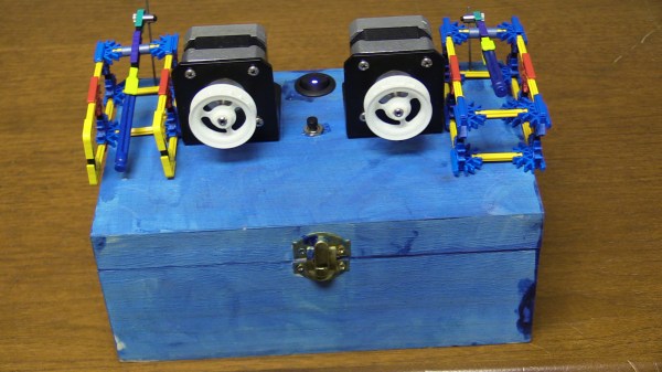
[Andreas] has created this tutorial on real-time (RT) tasks in Linux. At first blush that sounds like a rather dry topic, but [Andreas] makes things interesting by giving us some real-world demos using a Raspberry Pi and a stepper motor. Driving a stepper motor requires relatively accurate timing. Attempting to use a desktop operating system for a task like this is generally ill-advised. Accurate timing is best left to a separate microcontroller. This is why we often see the Raspi paired with an Arduino here on Hackaday. The rationale behind this is not often explained.

[Andreas] connects a common low-cost 28BYJ-48 geared stepper motor with a ULN2003 driver board to a Raspberry Pi’s GPIO pins. These motors originally saw use moving the louvers of air conditioners. In general, they get the job done, but aren’t exactly high quality. [Andreas] uses a simple program to pulse the pins in the correct order to spin the motor. Using an oscilloscope, a split screen display, and a camera on the stepper motor, [Andreas] walks us through several common timing hazards, and how to avoid them.

The most telling hazard is shown last. While running his stepper program, [Andreas] runs a second program which allocates lots of memory. Eventually, Linux swaps out the stepper program’s memory, causing the stepper motor to stop spinning for a couple of seconds. All is not lost though, as the swapping can be prevented with an mlockall() call.

The take away from this is that Linux is not a hard real-time operating system. With a few tricks and extensions, it can do some soft real-time tasks. The best solution is to either use an operating system designed for real-time operation, or offload real-time operations to a separate controller.

Continue reading “A Tutorial On Using Linux For Real-Time Tasks”

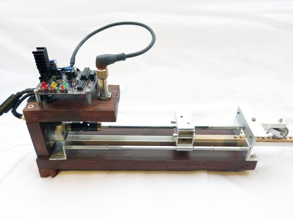
The Stepper Driver Driver

KONICA MINOLTA DIGITAL CAMERA

The Stepstick and Pololu motor drivers are the heart of just about every Reprap electronics board, but they can go bad. The usual way of testing these things is to rig up a microcontroller on a breadboard, grab some cables, and wire something up. [Ken]’s Easy Stepper Motor Controller is a much simpler solution to the problem of testing these drivers and could, with a bit of practice, be constructed on a single-sided homebrew PCB.

The Easy Stepper Motor Controller is a very simple board with connections to a motor, a power supply, and headers for a single Pololu or Stepstick motor driver. Two buttons and a pot control the rotation of the motor with the help of an ATtiny10, and jumpers for up to 16x microstepping are right there on the board.

There’s a video after the break showing what this stepper motor driver driver can do. It’s not much, but if you’re just testing a driver, it’s all you need.
Continue reading “The Stepper Driver Driver”

The Most Beautiful Floppy Disk Jukebox Ever

Playing music on floppy drives is something that has been done to death. [kiu]’s RumbleRail is something else entirely. Yes, it’s still a collection of floppy drives playing MIDI files, but the engineering and build quality that went into this build puts it in a class by itself.

Instead of the usual assemblage of wires, power cords, and circuits that accompany most musical floppy drive builds, [kiu]’s is an exercise in precision and modularity. Each of the eight floppy drives are connected to its own driver with an ATMega16 microcontroller on board. The microcontrollers in these driver boards receive orders from the command board over an I2C bus. Since everything on the RumbleRail is modular, and the fact [kiu] is using DIP switches to set the I2C address of each board, this build could theoretically be expanded to 127 voices, or 127 individual floppy drives each playing their part of a MIDI file.

The RumbleRail can also operate in a standalone mode without the need for a separate computer feeding it data. MIDI files can be loaded off an SD card by the main controller board, and decode them for the floppy drivers.

If you’d like to build your own RumbleRail, all the board files, schematics, and firmware are up on [kiu]’s git. There are, of course, a few videos below of the floppy jukebox in action.

Continue reading “The Most Beautiful Floppy Disk Jukebox Ever”

Electronic Phenakistoscope!

phenakistoscope

Looking for a clever way to build a Phenakistoscope? Maybe you’re more familiar with its other names; Fantoscope, Phantasmascope, or perhaps its close cousin the Zoetrope?

If you’re still scratching your head, that’s okay — they have really weird names. What we’re referring to here is a type of optical illusion that mimics movement by showing a series of still images at an offset interval — this can be achieved by looking through slots, strobing a light (like in this case) or even by the use of mirrors.

This particular Phenakistoscope is a very simple but clever design that makes use of a recycled stepper motor from a printer, a CD as the animation disk, a strip of LED lighting, a few potentiometers and an Arduino to control the strobe. It works by synchronizing the strobe frequency with the motor rotation, resulting in the image in motion effect.

Stick around after the break for a full gallery of the build and a demonstration video.

Continue reading “Electronic Phenakistoscope!”

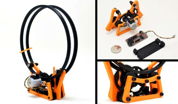
Four Cable Drawing Machine Pulls Our Strings

sandplotter

[David] has created a four cable drawing machine for the Telus Spark Science Centre in Canada. Hackaday has featured [David’s] unconventional drawing contraptions before, specifically his center pivot pen plotter. The drawing machine is a new take on a drawbot, and could be considered to be close cousins with [Dan’s] SkyCam. The premise is simple: A stepper motor with a reel of string is placed at each corner of a square. The strings for all four motors come together at a center weight. When all four strings are taut, the weight is lifted off the drawing surface. When a bit of slack is added into the strings, gravity pulls the weight down to touch the sand.

It’s at this point that a simple premise becomes a complex implementation. Moving the weight in one direction is a matter of reeling out string on one motor, and reeling in string on the other. But what about the two “un driven” strings? They have to be slack enough to allow movement in the driven direction, but not so slack that the weight can dig in and tumble on the sand, causing a tangle. To handle some of these questions, [David] called on [Kevin] to write some software. [Kevin] created a custom kinematics module for LinuxCNC to control the drawing machine. The drawing machine runs on Gerber Code, similar to a CNC. Simply feed the machine Cartesian coordinates, and [Kevin’s] module converts to steps.

Continue reading “Four Cable Drawing Machine Pulls Our Strings”