By the time colour TV came to the United Kingdom, it was old news to Americans. Most of the viewing public on the Western side of the Atlantic had had the opportunity to see more than black-and-white images for years when in 1967 the BBC started transmitting its first colour channel, BBC2.
For Americans and continental Europeans, the arrival of colour TV had been an incremental process, in which the colour subcarrier had been added to their existing transmission standard. Marketed as “compatible color” to Americans, this ensured that their existing black-and-white TV sets had no need for replacement as the new transmissions started.
The United Kingdom by contrast had been one of the first countries in the world to adopt a television standard in the 1930s, so its VHF 405-line positive-modulation black-and-white services stood alone and looked extremely dated three decades later. The BBC had performed experiments using modified round-CRT American sets to test the feasibility of inserting an NTSC colour subcarrier into a 405-line signal, but had eventually admitted defeat and opted for the Continental 625-line system with the German PAL colour encoding. This delivered colour TV at visibly better quality than the American NTSC system, but at the expense of a 15-year process of switching off all 405-line transmitters, replacing all 405-line sets, and installing new antennas for all viewers for the new UHF transmissions.
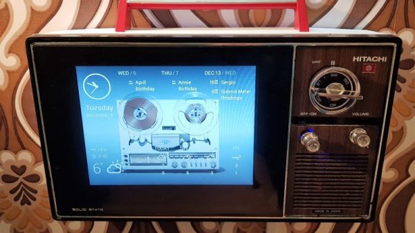
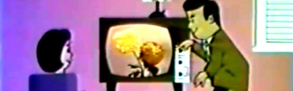
Such a significant upgrade must have placed a burden upon the TV repair and maintenance trade, because as part of the roll-out of the new standard the BBC produced and transmitted a series of short instructional animated films about the unfamiliar technology, which we’ve placed below the break. The engineer is taken through the signal problems affecting UHF transmissions, during which we’re reminded just how narrow bandwidth those early UHF Yagis must have been, then we are introduced to the shadowmask tube and all its faults. The dreaded convergence is introduced, as these were the days before precision pre-aligned CRTs, and we briefly see an early version of the iconic Test Card F. Finally we are shown the basic procedure for achieving the correct white balance. There is a passing reference to dual-standard sets, as if convergence for colour transmissions wasn’t enough of a nightmare a lot of the early colour sets incorporated a bank of switches on their PCB to select 405-line or 625-line modes. The hapless engineer would have to set up the convergence for both signals, something that must have tried their patience.
The final sequence looks at the hand-over of the new set to the customer. In an era in which we are used to consumer electronics with fantastic reliability we would not be happy at all with a PAL set from 1967. They were as new to the manufacturers as they were to the consumers, so the first generation of appliances could hardly have been described as reliable. The smiling woman in the animated film would certainly have needed to call the engineer again more than once to fix her new status symbol.
Continue reading “Retrotechtacular: Information From The Days When Colour TV Was New” →
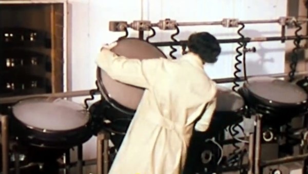
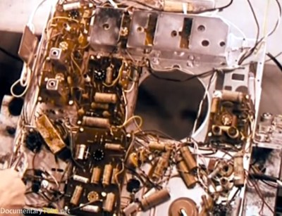 Right from the start the apparent chaos of the circuitry is mindboggling, with some components on circuit boards but many being wired point-to-point. The narrator even makes comments on the “new technique for making electrical connections” that uses a wire wrapping gun. The claim is that this is cleaner, faster, and neater than soldering. ([Bil Herd]