When we do textbook analysis, we tend to ignore the real-world concerns for the sake of learning. So, a typical theoretical voltage divider is simply two resistors. But if you examine a low-pass RC filter, you’ll see a single resistor and a capacitor. What if you combine them? That’s what [Old Hack EE] did in a recent video, and you can check it out below.
It helps if you are familiar with Thevenin equivalents and, of course, Ohm’s Law. There’s also a bit of algebra, but nothing too complicated. The example design has a lossy filter at 100 Hz.
Of course, RC filters are easy to understand if you think of them as voltage dividers with a frequency-variable resistance, which is what the math is basically saying. The load impedance, in this case, is R2 in parallel with Xc at a given frequency.
He mentions that you might find a circuit like this in a power supply. However, it is also common to see this circuit wherever a divider drives a load with capacitance or even parasitic capacitance in cables or circuit boards.
We are always impressed with something so simple can actually be so complex. For example, what would you think goes into an analog computer? Of course, a “real” analog computer has opamps that can do logarithms, square roots, multiply, and divide. But would it surprise you that you can make an analog device like a slide rule using a Wheatstone bridge — essentially two voltage dividers. You don’t even need any active devices at all. It is an old idea and one that used to show up in electronic magazines now and again. I’ll show you how they work and simulate the device so you don’t have to build it unless you just want to.
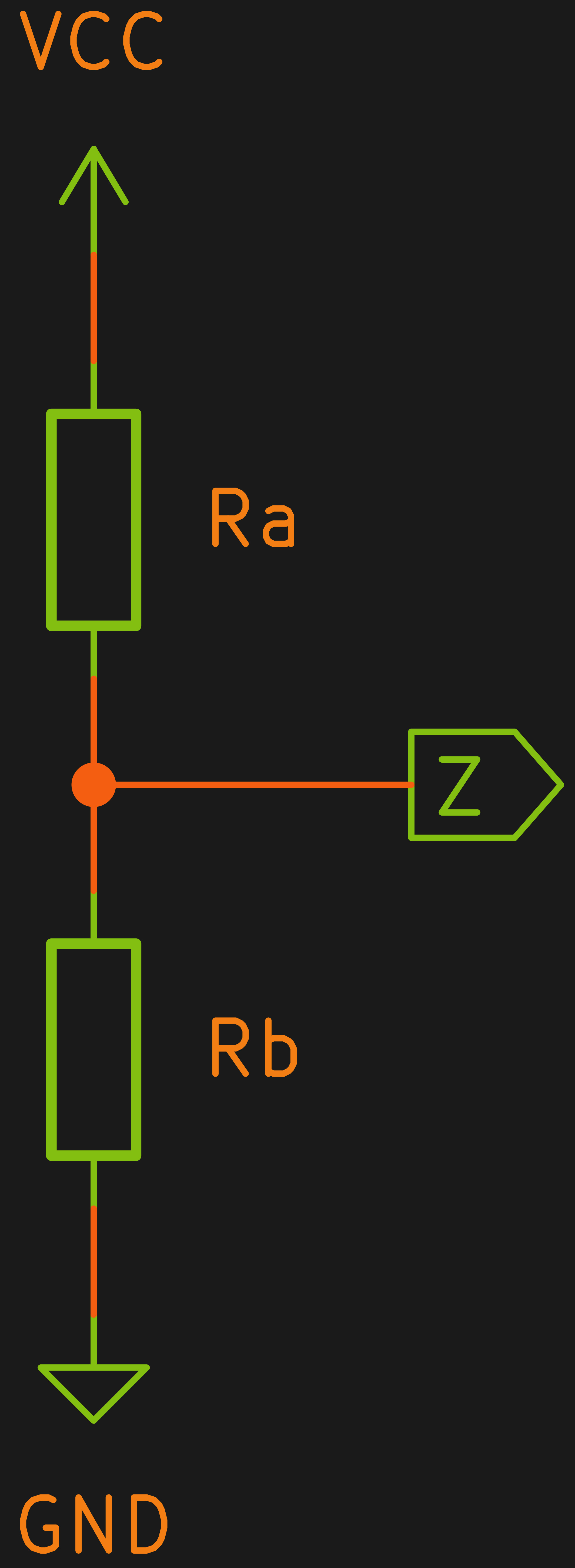
A voltage divider is one of the easiest circuits in the world to analyze. Consider two resistors Ra and Rb in series. Voltage comes in at the top of Ra and the bottom of Rb is grounded. The node connecting Ra and Rb — let’s call it Z — is what we’ll consider the output.
Let’s say we have a 10 V battery feeding A and a perfect voltmeter that doesn’t load the circuit connected to Z. By Kirchoff’s current law we know the current through Ra and Rb must be the same. After all, there’s nowhere else for it to go. We also know the voltage drop across Ra plus the voltage drop across Rb must equal to 10 V. Kirchoff, conservation of energy, whatever you want to call it. Let’s call these quantities I, Va, and Vb. Continue reading “Circuit VR: The Wheatstone Bridge Analog Computer”→
There’s certainly no shortage of “smart” gadgets out there that will provide you with a notification, or even a live audiovisual stream, whenever somebody is at your door. But as we’ve seen countless times before, not everyone is thrilled with the terms that most of these products operate under. Getting a notification on your phone when the pizza guy shows up shouldn’t require an email address, credit card number, or DNA sample.
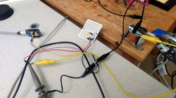
For [Nick Touran], half the work was already done. There was already a traditional wired doorbell in his home, he just had to come up with a minimally invasive way to link it with Home Assistant. He reasoned that he could tap into the low-voltage side of the doorbell transformer and watch for the telltale fluctuations that would indicate the bell was doing its thing. The ESP8266 has an ADC to measure voltage and WiFi to connect to Home Assistant, so it seemed like the perfect bridge between old and new.
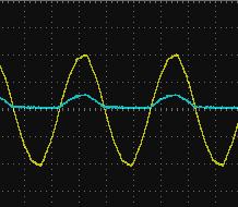
Transformer voltage before and after
Of course, as with any worthwhile project, it ended up being a bit more complicated. Wired doorbells generally operate on 16-24 VAC, and [Nick] knew if he tried to put his Wemos D1 across the line he’d release the critical Magic Smoke. What he needed was a voltage divider circuit that would take low-voltage AC and drop it to an even lower DC voltage that the microcontroller could cope with.
The simple circuit [Nick] comes up with cuts the voltage way down and removes the negative component completely. So what was originally 18.75 VAC turned into a series of 60 Hz blips at 2.4 VDC; perfect for feeding into a microcontroller ADC. With a baseline to work from, he could then write some code that would watch for variations in this signal to determine when the bell was ringing.
Or at least, that was the idea. While the setup worked well enough on the bench, its performance in the real-world left something to be desired. If his house guest had a heavy hand, it worked great. But a quick tap of the doorbell button would tend to go undetected. After investigating the issue, [Nick] found that he needed to use some software trickery to ensure the ESP8266 was able to keep up with the speedy signal. Once he was able to reliably detect short and long button presses, the rest was just a simple matter of sending an MQTT message to his automation system.
One way to understand how the 555 timer works and how to use it is by learning what the pins mean and what to connect to them. A far more enjoyable, and arguably a more useful way to learn is by looking at what’s going on inside during each of its modes of operation. [Dejan Nedelkovski] has put together just such a video where he walks through how the 555 timer IC works from the inside.
We especially like how he immediately removes the fear factor by first showing a schematic with all the individual components but then grouping them into what they make up: two comparators, a voltage divider, a flip-flop, a discharge transistor, and an output stage. Having lifted the internals to a higher level, he then walks through examples, with external components attached, for each of the three operating modes: bistable, monostable and astable. If you’re already familiar with the 555 then you’ll enjoy the trip down memory lane. If you’re not familiar with it, then you soon will be. Check out his video below.
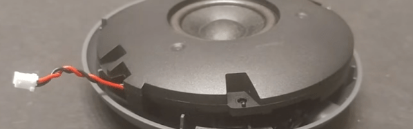
Even if you don’t want to add an AUX audio output port to your Google Home Mini, you’ll still want to see a pair of videos from [SnekTek]. After all, you’ll eventually want to open it up, and putting it over some boiling water might not have been your first idea. You can see both videos, below.
However, he did want to add an AUX port. The biggest challenge was finding a place to put the connector. Even after identifying a likely spot, a bolt interfered with the case closing and so he removed it. The one bolt didn’t seem to bother the final result.
I work a lot with high voltages and others frequently replicate my projects, so I often get asked “What voltage is needed?”. That means I need to be able to measure high voltages. Here’s how I do it using a Fluke high voltage probe as well as my own homemade probe. And what if you don’t have a probe? I have a solution for that too.
How Long Is Your Spark?
The simplest way to measure high voltage is by spark length. If your circuit has a spark gap then when a spark occurs, that’s a short-circuit, dumping all your built up charge. When your spark gap is at the maximum distance at which you get a spark then just before the spark happens is when you have your maximum voltage. During the spark the voltage rapidly goes to zero and depending on your circuit it may start building up again. The voltage before the spark occurred is related to the spark length, which is also the spark gap width.
The oscilloscope photo below shows this changing voltage. This method is good for a rough estimate. I’ll talk about doing more precise measurements when I talk about high voltage probes further down.
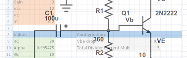
Last time I showed you how to set up a reasonably complex design in a spreadsheet: a common emitter bipolar transistor amplifier. Having the design in a spreadsheet makes it easy to do “what if” scenarios and see the effects on the design almost immediately.
Another advantage that spreadsheets offer is a way to “solve” or optimize equations. That can be very useful once you have your model. For Excel, you need to install the Solver add-in (go to the Excel Options dialog, select Manage Add-Ins, and select the Solver Add-In). You might also enjoy OpenSolver. You can even get that for Google Sheets (although it currently lacks a non-linear solver which makes it less useful for what we need).