Logic Analyzers: Decoding And Monitoring

Last time, we looked into using a logic analyzer to decode SPI signals of LCD displays, which can help us reuse LCD screens from proprietary systems, or port LCD driver code from one platform to another! If you are to do that, however, you might find a bottleneck – typically, you need to capture a whole bunch of data and then go through it, comparing bytes one by one, which is quite slow. If you have tinkered with Pulseview, you probably have already found an option to export decoded data – all you need to do is right-click on the decoder output and you’ll be presented with a bunch of options to export it. Here’s what you will find:

2521888-2521888 I²C: Address/data: Start
2521896-2521947 I²C: Address/data: Address write: 22
2521947-2521954 I²C: Address/data: Write
2521955-2521962 I²C: Address/data: ACK
2521962-2522020 I²C: Address/data: Data write: 01
2522021-2522028 I²C: Address/data: ACK
2522030-2522030 I²C: Address/data: Start repeat
2522038-2522089 I²C: Address/data: Address read: 22
2522089-2522096 I²C: Address/data: Read
2522096-2522103 I²C: Address/data: ACK
2522104-2522162 I²C: Address/data: Data read: 91
2522162-2522169 I²C: Address/data: NACK
2522172-2522172 I²C: Address/data: Stop

Whether on the screen or in an exported file, the decoder output is not terribly readable – depending on the kind of interface you’re sniffing, be it I2C, UART or SPI, you will get five to ten lines of decoder output for every byte transferred. If you’re getting large amounts of data from your logic analyzer and you want to actually understand what’s happening, this quickly will become a problem – not to mention that scrolling through the Pulseview window is not a comfortable experience.

The above output could look like this: 0x22: read 0x01 ( DEV_ID) = 0x91 (0b10010001). Yet, it doesn’t, and I want to show you how to correct this injustice. Today, we supercharge Pulseview with a few external scripts, and I’ll show you how to transfer large amounts of Sigrok decoder output data into beautiful human-readable transaction printouts. While we’re at it, let’s also check out commandline sigrok, avoiding the Pulseview UI altogether – with sigrok-cli, you can easily create a lightweight program that runs in the background and saves all captured data into a text file, or shows it on a screen in realtime! Continue reading “Logic Analyzers: Decoding And Monitoring”

Decoding The 8088

There is a lot to like about open software, and in some areas, a well-thought-out piece of software can really make a huge impact. A great example of this is the Sigrok project. Creating simple devices that act like a logic analyzer is relatively easy. What’s hard is writing nice software for such a setup including protocol decoders. Sigrok has done it and since it is open, you can add your device and decode your protocol. [GloriousCow] had done the hardware part of interfacing to the 8088 in an IBM PC using an off-the-shelf logic analyzer that uses a customized version of Sigrok. But the output was a CSV file you had to process in a spreadsheet program. The next step: write a decoder for Sigrok to understand 8088 bus cycles.

The post covers the details of writing such a plug-in for Pulseview, the Sigrok GUI. It will also work for the command line interface if you prefer that. The code is in Python.

Continue reading “Decoding The 8088”

Agreeing By Disagreeing

While we were working on the podcast this week, Al Williams and I got into a debate about the utility of logic analyzers. (It’s Hackaday, after all.) He said they’re almost useless these days, and I maintained that they’re more useful than ever. When we got down to it, however, we were actually completely in agreement – it turns out that when we said “logic analyzer” we each had different machines, and use cases, in mind.

Al has a serious engineering background and a long career in his pocket. When he says “logic analyzer”, he’s thinking of a beast with a million probes that you could hook up to each and every data and address line in what would now be called a “retrocomputer”, giving you this god-like perspective on the entire system state. (Sounds yummy!) But now that modern CPUs have 64-bits, everything’s high-speed serial, and they’re all deeply integrated on the same chip anyway, such a monster machine is nearly useless.

Meanwhile, I’m a self-taught hacker type. When I say “logic analyzer”, I’m thinking maybe 8 or 16 signals, and I’m thinking of debugging the communications between a microcontroller, an IMU, or maybe a QSPI flash chip. Heck, sometimes I’ll even break out a couple pins on the micro for state. And with the proliferation of easy and cheap modules, plus the need to debug and reverse commodity electronics, these logic analyzers have never been more useful.

So in the end, it was a simple misunderstanding – a result of our different backgrounds. His logic analyzers were extinct or out of my price range, and totally off my radar. And he thinks of my logic analyzer as a “simple serial analyzer”. (Ouch! But since when are 8 signals “serial”?)

And in the end, we both absolutely agreed on the fact that great open-source software has made the modern logic analyzers as useful as they are, and the lack thereof is also partially responsible for the demise of the old beasts. Well, that and he needs a lab cart then to carry around what I can slip in my pocket today. Take that!

Logic Analyzers: Tapping Into Raspberry Pi Secrets

Today, I’d like to highlight a tool that brings your hacking skills to a whole new level, and does that without breaking the bank – in fact, given just how much debugging time you can save, how many fun pursuits you can unlock, and the numerous features you can add, this might be one of the cheapest tools you will get. Whether it’s debugging weird problems, optimizing your code, probing around a gadget you’re reverse-engineering, or maybe trying to understand someone’s open-source library, you are likely missing out a lot if you don’t have a logic analyzer on hand!

It’s heartbreaking to me that some hackers still don’t know the value that a logic analyzer brings. Over and over again, tactical application of a logic analyzer has helped me see an entirely different perspective on something I was hacking on, and that’s just the thing I’d like to demonstrate today.

Diving In

A logic analyzer has a number of digital inputs, and it continuously reads the state of these digital inputs, sending them to your computer or showing them on a screen – it’s like a logic-level-only oscilloscope. If you have an I2C bus with one MCU controlling a sensor, connect a logic analyzer to the clock and data pins, wire up the ground, launch the logic analyzer software on your computer, and see what’s actually happening.

For instance, have you ever noticed the ID_SC and ID_SD pins on the Raspberry Pi GPIO connector? Are you wondering what they’re for? Don’t you want to check what actually happens on these pins? Let’s do that right now! Continue reading “Logic Analyzers: Tapping Into Raspberry Pi Secrets”

DisplayPort: Tapping The Altmode

Really, the most modern implementation of DisplayPort is the USB-C DisplayPort altmode, synonymous with “video over USB-C”, and we’d miss out if I were to skip it. Incidentally, our last two articles about talking USB-PD have given a few people a cool new toy to play with – people have commented on the articles, reached out to me for debugging help, and I’ve even seen people build the FUSB302B into their projects! Hot on the heels of that achievement, let’s reach further and conquer one more USB-C feature – one that isn’t yet openly available for us to hack on, even though it deserves to be.

For our long-time readers, it’s no surprise to see mundane capabilities denied to hackers. By now, we all know that many laptops and phones let you get a DisplayPort connection out of a USB-C port. Given that the USB-C specifications are openly available, and we’ve previously implemented a PD sink using those specifications, you’d expect that we could do DisplayPort with the same ease. Yet, the DisplayPort altmode specification is behind a VESA membership paywall, with a hefty pricetag – a practice of theirs that has been widely criticized, counter to their purpose as a standards organization and having resulted in some of their standards failing.

Not to worry, however – we can easily find an assortment of PDFs giving a high-level overview and some details of the DisplayPort altmode, and here’s my favorite! I also have a device running MicroPython with a FUSB302 chip connected, and a few DisplayPort altmode devices of mine that I can disassemble. This, turns out, is more than enough for us to reverse-engineer our way into an open-source DisplayPort altmode library!

Continue reading “DisplayPort: Tapping The Altmode”

Linux Fu: Eavesdropping On Serial

In the old days, if you wanted to snoop on a piece of serial gear, you probably had a serial monitor or, perhaps, an attachment for your scope or logic analyzer. Today, you can get cheap logic analyzers that can do the job, but what if you want a software-only solution? Recently, I needed to do a little debugging on a USB serial port and, of course, there isn’t really anywhere to easily tie in a monitor or a logic analyzer. So I started looking for an alternate solution.

If you recall, in a previous Linux Fu we talked about pseudoterminals which look like serial ports but actually talk to a piece of software. That might make you think: why not put a piece of monitor software between the serial port and a pty? Why not, indeed? That’s such a good idea that it has already been done. When it works, it works well. The only issue is, of course, that it doesn’t always work.

Continue reading “Linux Fu: Eavesdropping On Serial”

Pico Makes Capable Logic Analyzer

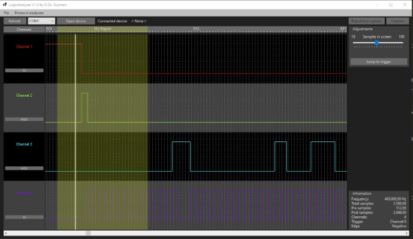
A common enough microcontroller project is to create some form of logic analyzer. In theory, it should be pretty easy: grab some digital inputs, store them, and display them. But, of course, the devil is in the details. First, you want to grab data fast, but you also need to examine the trigger in real time — hard to do in software. You may also need input conditioning circuitry unless you are satisfied with the microcontroller’s input characteristics. Finally, you need a way to dump the data for analysis. [Gusmanb] has tackled all of these problems with a simple analyzer built around the Raspberry Pi Pico.

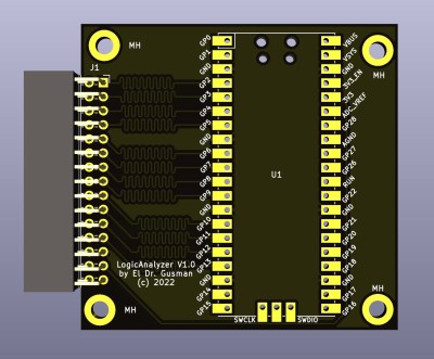
On the front and back ends, there is an optional board that does fast level conversion. If you don’t mind measuring 3.3 V inputs, you can forego the board. On the output side, there is custom software for displaying the results. What’s really interesting, though, is what is in between.

The simple PCB is completely optional.

The Pico grabs 24 bits of data at 100 MHz and provides edge and pattern triggers. This is impressive because you need to look at the data as you store it and that eats up a few instruction cycles if you try to do it in software, dropping your maximum clock rate. So how does this project manage it?

It uses the Pico’s PIO units are auxiliary dedicated processors that aren’t very powerful, but they are very fast and deterministic. Two PIO instructions are enough to handle the work for simple cases. However, there are two PIOs and each has four separate state machines. It still takes some work, but it is easier than trying to run a CPU at a few gigahertz to get the same effect. The fast trigger mode, in particular, abuses the PIO to get maximum speed and can even work up to 200 MHz with some limitations.

If you want to try it, you can use nothing more than a Pico and a jumper wire as long as you don’t need the level conversion. The project page mentions that custom software avoids using OpenBench software, which we get, but we might have gone for Sigrok drivers to prevent having to reinvent too many wheels. The author mentions that it was easier to roll your own code than conform to a driver protocol and we get that, too. Still, the software looks nice and even has an SPI protocol analyzer. It is all open source, so if you want other protocols before the author gets to them, you could always do it yourself.

If you do want a Pico and Sigrok, we’ve covered a project that does just that. Most of the logic analyzers we use these days we build into our FPGA designs.