Interfacing The Sidewinder Joystick To AVRs

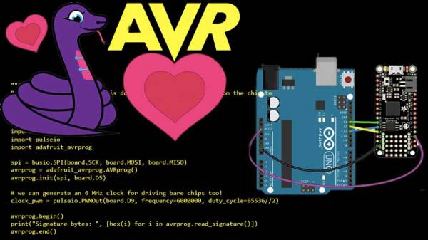
The Sidewinder line was a series of gaming peripherals produced by Microsoft, starting in the 1990s. After some initial stumbles, several cutting edge joysticks were released, at a time when the home computer market was in a state of flux, transitioning from legacy interfaces like serial and parallel to the more modern USB. In this interim period, Sidewinder joysticks used a special method to communicate digitally over the game port interface, which more typically used a kludge to read joysticks in an analog manner. [MaZderMind] managed to reverse engineer this protocol, and implemented the interface on an AVR microcontroller.

The technology is loosely described in US Patent 5628686, which discusses the method used to communicate bidirectionally with the Sidewinder joystick. [MaZderMind] found that the patent documents didn’t correspond exactly with how the Sidewinder Precision Pro communicated, but it was close enough that the operation could be reverse engineered.

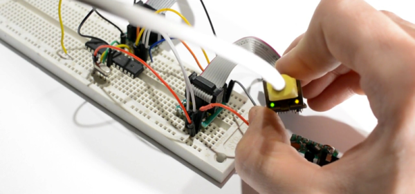
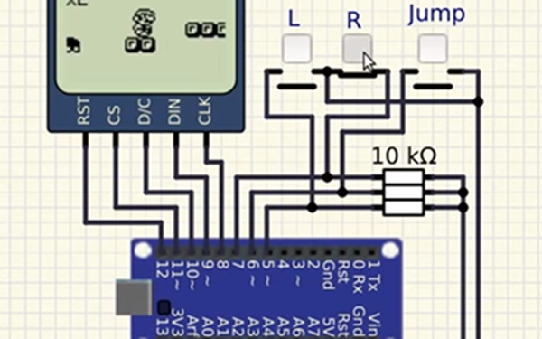
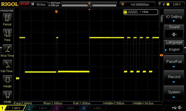
The plan is to use the vintage joystick to control a quadcopter, so the interface was implemented on an AVR, and a graphical LCD installed to act as a display for testing the operation. [MaZderMind] also captured data on an oscilloscope to indicate in detail the quirks of the joystick’s operation.

Yes, it’s entirely possible to use a more modern microcontroller with a USB joystick. However, there are few that measure up to the standards of the old Sidewinder hardware, and sometimes the best tool for the job is the one you’ve got with you. A traditional single joystick is a different take on quadcopter control, but there’s other options – gesture control is possible, too.


Negative Voltage Pushes AVR To New Heights

If we say that a hacker is somebody who looks at a “solved” problem and can still come up with multiple alternative solutions, then [Charles Ouweland] absolutely meets the grade. Not that we needed more evidence of his hacker cred given what we’ve seen from him before, but he recently wrote in to tell us about an interesting bit of problem solving which we think is a perfect example of the principle. He wanted to drive a salvaged seven segment LED display with an AVR microcontroller, but there was only one problem: the display needs 15V but the AVR is only capable of 5V. So what to do?

As it turns out, the first step to solving the problem was verifying there was actually a problem to begin with. [Charles] did some experimentation and found that the display didn’t actually need 15V to operate, and in fact would light up well enough at just 6.5V. This lowered the bar quite a bit, but it was still too high to power directly from the chip.

There were a few common ways to solve this problem, which no doubt the Hackaday reader is well aware of. But [Charles] wanted to take the path less traveled. More specifically, the path with the least amount of additional components he had to put on his PCB. He set out to find the absolute easiest way to make his 5V AVR light up a 6.5V LED, and ended up coming with a very clever solution that some may not even know is possible.

He reasoned that if he connected the source pins of two BS170 MOSFETs to a voltage of -1.5V, even when the AVR pin was 0V, they would be still be receiving 1.5V. This virtual “step ladder” meant that once the AVR’s pin goes high (5V), the relative voltage would actually be 6.5V and enough to drive his LEDs. Of course the only problem with that is that you need to have a source for -1.5V.

Getting a negative voltage would normally require adding more components to the design (which he set out to avoid in the first place), but then he came up with another clever idea. To pull the trick off, he actually feeds the AVR 6.5V, but raises the ground voltage by 1.5V with the addition of two 1N4007 diodes. This way the AVR gets a voltage within its capabilities and still can provide a relative 6.5V to the LEDs.

One might say [Charles] took the Kobayashi Maru approach, and simply redefined the rules of the game. But such is the power of the confounding negative voltage.

Want To Learn Ethernet? Write Your Own Darn AVR Bootloader!

There’s a school of thought that says that to fully understand something, you need to build it yourself. OK, we’re not sure it’s really a school of thought, but that describes a heck of a lot of projects around these parts.

[Tim] aka [mitxela] wrote kiloboot partly because he wanted an Ethernet-capable Trivial File Transfer Protocol (TFTP) bootloader for an ATMega-powered project, and partly because he wanted to understand the Internet. See, if you’re writing a bootloader, you’ve got a limited amount of space and no device drivers or libraries of any kind to fall back on, so you’re going to learn your topic of choice the hard way.

[Tim]’s writeup of the odyssey of cramming so much into 1,000 bytes of code is fantastic. While explaining the Internet takes significantly more space than the Ethernet-capable bootloader itself, we’d wager that you’ll enjoy the compressed overview of UDP, IP, TFTP, and AVR bootloader wizardry as much as we did. And yes, at the end of the day, you’ve also got an Internet-flashable Arduino, which is just what the doctor ordered if you’re building a simple wired IoT device and you get tired of running down to the basement to upload new firmware.

Oh, and in case you hadn’t noticed, cramming an Ethernet bootloader into 1 kB is amazing.

Speaking of bootloaders, if you’re building an I2C slave device out of an ATtiny85¸ you’ll want to check out this bootloader that runs on the tiny chip.

New AVR-IOT Board Connects To Google

Readers of Hackaday are no strangers to using a microcontroller to push data to WiFi. Even before the ESP8266 there were a variety of ways to do that. Now Microchip is joining the fray with a $29 board called the AVR-IOT WG that contains an 8-bit ATmega4808, a WiFi controller, and hardware-based crypto chip for authenticating with Google Cloud.

The board has a section with a USB port for charging a battery and debugging that looks like it is made to cut away. There are a number of LEDs and buttons along with a light sensor and a temperature sensor. It feels like the goal here was to pack as many Microchip parts onto a single dev board as possible. You’ll find the ATmega4808 as the main controller, an ATWINC1510 WiFi controller (a castellated module reminiscent of the ESP8266), the ATECC608A cryptographic co-processor, MCP73871 LiPo charger, MIC33050 voltage regulator, and an MCP9808 temperature sensor. We can’t find much info about the “nEDBG Programmer/Debugger” chip. If you’ve used it on one of a handful of other dev board, let us know in the comments about off-board programming and other possible hacks.

Naturally, the board works with AVR Studio or MPLAB X IDE (Microchip bought Atmel, remember?). Of course, Atmel START or MPLAB Code Configurator can configure the devices, too. There’s also an AVR-IoT-branded website that lets you use Google cloud to connect your device for development. The headers along the top and bottom edges are compatible with MicroElektronika Click boards which will make anyone with a parts bin full of those happy.

Looks like you can pick up the Microchip boards now from the usual places. From reading what Microchip is saying, they would like to position this as the “IoT Arduino” — something someone without a lot of experience could pick up and use to pipe data into Google cloud. While that’s probably good, it isn’t that hard to use an ESP-device to do the same thing using the Arduino IDE and then you have a 32-bit processor and you can use whatever cloud vendor you want. Sure, it would be a little more work, so maybe that’s where this offering will appeal.

On the plus side, we really liked that there was a battery option with a charger already on board — it seems like that’s something we always have to add anyway. It may be buried in the documentation, but the user’s guide and the technical guide didn’t appear to have an average and maximum current draw specified, so battery life is an open question, although the video says “low power.”

Although it isn’t quite the same thing, we’ve seen ESP8266’s talk to Google servers for interfacing with Google Home. And while it is on the Amazon cloud, we’ve even seen a 6502 up there.

Continue reading “New AVR-IOT Board Connects To Google”

Simulate PIC And Arduino/AVR Designs With No Cloud

I’ve always appreciated simulation tools. Sure, there’s no substitute for actually building a circuit but it sure is handy if you can fix a lot of easy problems before you start soldering and making PCBs. I’ve done quite a few posts on LTSpice and I’m also a big fan of the Falstad simulator in the browser. However, both of those don’t do a lot for you if a microcontroller is a major part of your design. I recently found an open source project called Simulide that has a few issues but does a credible job of mixed simulation. It allows you to simulate analog circuits, LCDs, stepper and servo motors and can include programmable PIC or AVR (including Arduino) processors in your simulation.

The software is available for Windows or Linux and the AVR/Arduino emulation is built in. For the PIC on Linux, you need an external software simulator that you can easily install. This is provided with the Windows version. You can see one of several videos available about an older release of the tool below. There is also a window that can compile your Arduino code and even debug it, although that almost always crashed for me after a few minutes of working. As you can see in the image above, though, it is capable of running some pretty serious Arduino code as long as you aren’t debugging.

Continue reading “Simulate PIC And Arduino/AVR Designs With No Cloud”

Dissecting The AVR DebugWire

Anyone who’s ever written more than a dozen or so lines of code knows that debugging is a part of life in our world. Anyone who’s written code for microcontrollers knows that physical debugging is a part of our life as well. Atmel processors use a serial communications protocol called debugWire, which is a simpler version of JTAG and allows full read/write access to all registers and allows one to single step, break, etc. [Nerd Ralph], a prominent fixture here at Hackaday has dug into the AVR debugWire protocol and enlightened us with some valuable information.

While the protocol side of debugWire is a mostly-solved problem, the physical layer was giving him trouble. He started with a diode, and then went through a couple resistors and other components to interface with the debugWire pin on the AVR microcontroller, doing most of the troubleshooting work so now you don’t have to. He notes that interface components might need to be tailored to specific USB-TTL adapters, so keep that in mind if you care to delve into working with debugWire yourself.

We’re no strangers to debugging techniques here at Hackaday. As always, be sure to let us know if you run across any new techniques or try anything new yourself!

MicroPython Learns A New Trick – ISP For AVRs

One of the reasons why the Arduino became so popular was the ability to program it with ease. It meant the end of big parallel programmers that would cost an arm and a leg. The latest installment of CircuitPython from [Lady Ada] and the team over at Adafruit is a library for programming AVR microcontrollers without a dedicated PC.

For the uninitiated, in-system programming or ISP for AVR controllers employ the SPI bus to write the compiled binary to the flash memory of the controller. The discount on the number of pins used itself is a benefit though getting the timings right was a bit tricky in the good old days. Most dedicated ISPs handle this nicely, though they are normally slaves to a host PC where an ‘upload’ button initiates the process.

With CircuitPython (a derivative of MicroPython), programming microcontrollers does not require going through the code-compile-flash cycle. It can be run on a number of processors, however, AVRs are not among them so this neat little library offers the next best thing. Wire-up an Atmega328P or ATmega2560 to a board like the ESP8266 that does run CircuitPython, and you can write firmware on the fly.

There is a complete tutorial on the subject thanks to [Phillip Torrone] and [Lady Ada] which includes some demo files for testing out the functionality. This opens up a lot of possibilities where OTA firmware updates for an AVR co-processor. We expect to see some keychain AVR programmers in the near future taking a hint from the ESP8266 based Two-Factor Authentication featured previously.