We’ve all got projects kicking around that we haven’t had time to document for our own purposes, let alone expose to the blinding light of the Internet. There are only so many hours in a day, and let’s face it, building the thing is a lot more fun than taking pictures of it. It took [Matthew Millman] the better part of a decade to combine everything he’s learned over the years to finally document the definitive version of his open source intelligent fan controller, but looking at the final result, we’re glad he did.
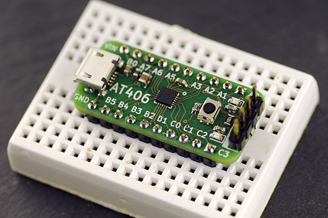
At the heart of this board is an ATmega328P, but don’t call it an Arduino. [Matthew] makes it very clear that if you want to hack around with the code for this project, you’re going to need to not only have a programmer for said chip, but know your way around AVR-GCC. He’s provided pre-built binaries for those content to run with the default settings, but you’ve still got to get it flashed onto the chip yourself. The project is designed to use the common DS18B20 temperature sensor, and as an added bonus, the firmware can even check if yours is a bootleg (spoilers: there’s an excellent chance it is).
Arguably the most interesting feature of this fan controller is its command line interface. Just plug into the serial port on the board, open your terminal emulator, and you’ll have access to a concise set of functions for querying the sensors as well as setting temperature thresholds and RPM ranges for the fans. There’s even a built-in “help” function should you forget a command or the appropriate syntax.
Originally [Matthew] developed this project as a way to control multiple fans inside of a PC case, but naturally, things have changed quite a bit since those early days. While today there’s no shortage of fancy controllers that can handle throttling an array of fans based on the internal temperature of your rig, there’s still something to be said for rolling your own solution. More importantly, there’s certainly other potential uses for a fully open source programmable fan controller.


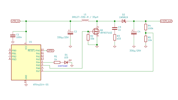
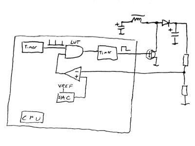 This napkinCAD sketch shows how [SM6VFZ] implemented the boost regulator in the ATtiny214. The AND gate is formed using one of the CCL LUT’s. The first “timer 1” on the left, connected to one input of the AND gate, is free running and set at 33 kHz. The analog comparator compares the boosted output voltage against an internally generated reference voltage derived from the DAC. The output of the comparator then “gates” timer 1 signal to trigger the second “timer 2” — which is a mono-shot timer set to max out at 15 us. This makes sure there is enough time left for the inductor to completely release its energy before the next cycle starts. You can check out the code that [SM6VFZ] used to built this prototype, and his generous amounts of commenting makes it easy to figure out how it works.