Wristwatches come in many shapes, sizes, and types, but most still have at least one thing in common: they feature a battery that needs to be swapped or recharged somewhere been every other day and every few years. A rare few integrate a solar panel that keeps the internal battery at least somewhat topped up, as environmental light permits.
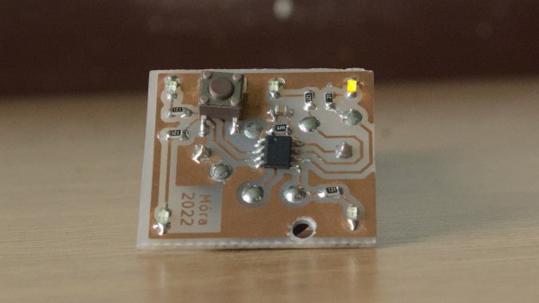
This “Perpetual” wristwatch designed by [Serhii Trush] aims to keep digitally ticking along using nothing but the integrated photodiodes, a rechargeable LIR2430 cell, and a power-sipping face that uses one LED for each hour of the day.
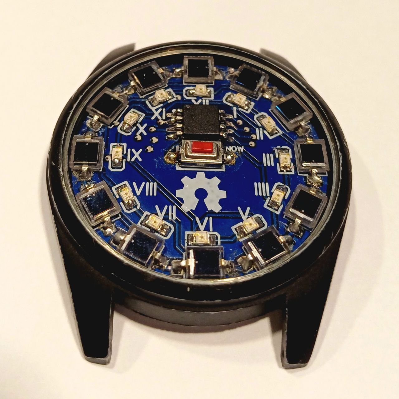
The wristwatch’s operation is demonstrated in the linked video (in Ukrainian, auto-generated subtitles available): to read out the current time, the button in the center is pressed, which first shows the hour, then the minutes (in 5 minute intervals).
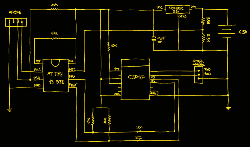
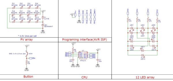
After this the ATtiny13 MCU goes back to sleep, briefly waking up every 0.5 seconds to update the time, which explains why there’s no RTC crystal. The 12 BPW34S photodiodes are enough to provide 2 mA at 0.5 V in full sunlight, which together keep the LIR2430 cell charged via a Zener diode.
As far as minimalistic yet practical designs go, this one is pretty hard to beat. If you wish to make your own, all of the design files and firmware are provided on the GitHub page.
Although we certainly do like the exposed components, it would be interesting to see this technique paired with the PCB watch face we covered recently.
Continue reading “A Solar-Powered Wristwatch With An ATtiny13”