When we first saw [Maarten Tromp]’s article about a “momentary latching switch” for guitar effects pedals, we have to admit to being a bit confused. When it comes to push-button switches, “momentary” and “latching” seem to be at odds with each other, with different mechanisms inside the switch to turn one into the other. What gives?
As it turns out, [Maarten]’s build makes perfect sense when you consider the demands of a musical performance. Guitar effects pedals, or “stomp boxes,” are often added to the output of electric guitars and other instruments to change the signals in some musically interesting way. The trouble is, sometimes you only need an effect for a few bars, and the push-on, push-off switches on many effects pedals make that awkward.
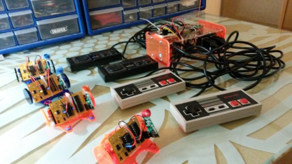
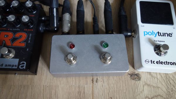
[Maarten]’s idea was to build a stomp box with momentary switches that act as inputs to an ATtiny2313 microcontroller rather than directly controlling the effect. That way, a bit of code can determine how long the switch is tapped, and activate a relay to do the actual switching accordingly. A short tap of the button tells the microcontroller to latch the relay closed until another tap comes along; a long press means that the relay is held open only as long as the button is held down.
Yes, he could have used a 555, a fact which [Maarten] readily acknowledges, but with some loss of flexibility; he currently has the threshold set at 250 milliseconds, which works for his performance style. Changing it would be a snap in code, as would toggling the latching logic. A microcontroller also makes expansion from the two-channel setup shown here easier.
Looking for more effects pedal action? We’ve got a bunch — a tube-amp tremolo, an Arduino Mega multipedal, a digital delay line. Take your pick!


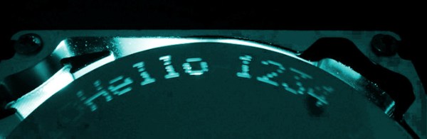
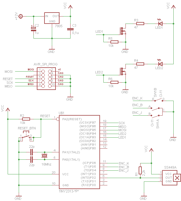 He used the frame, disk and motor from a drive and added LEDs under the spinning disk as the light source. The disk has 8 small holes drilled equidistant around the disk, and spiraling slightly toward the center. As the holes pass by the LEDS they are flashed by the ATtiny2313 processor to create images. To determine the position of the platters a Hall effect sensor is monitored by the 2313 to detect a magnet on the underside of the disk. There is room to display ten characters at one time. Each cursor position can scroll through the character set by rotating an encoder. For all the precision needed to coordinate the LEDs with the spinning holes the electronics and software code are amazingly simple. That’s a really nice job, [Adam]!