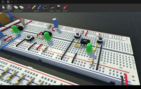
3D-Printed, Hot-Swap Keyboard PCB Generator Is Super Cool

About a month ago, [50an6xy06r6n] shared their hot swap 3D-printed circuit board for keyboard design with the mechanical keyboard subreddit. It’s more of a prototyping tool than a permanent fixture, though nothing is stopping you from using it permanently. Well, now it’s even better, and open source to boot.

[50an6xy06r6n] came up with this to test split ergo layouts faster and not have to solder anything — the switch pins make contact with the row wires and folded diode legs. In fact, prepping all the diodes is probably the thing that takes the longest.

The design can be generated from layout data, or you can convert directly from a KLE JSON file. We love how delightfully clean this keyboard breadboard generator looks, and we wish we had thought of it!

[50an6xy06r6n]’s PCB generator currently supports Cherry MX/clones and Kailh Choc switch footprints. If you want ALPS, somebody’s gonna have to send [50an6xy06r6n] some ALPS to make that happen.

As long as all the contact points are good, you should be able to use this as the final PCB indefinitely. We’ve certainly seen our share of 3D-printed wire guides. Really, you could print the whole thing, including the switches.

Silicon Jumpers Make This Wire-Free Breadboard Programmable

There’s no doubting the utility of the trusty solderless breadboard, but you have to admit they’re less than perfect. They’re not ideal for certain types of circuits, of course, but that’s less of a problem than those jumper wires. The careless will end up with their components hopeless tangled in a rat’s nest of jumpers, while the fastidious will spend far more time making the jumpers neat and tidy than actually prototyping the circuit itself. What to do?

One way to crack this nut is to make the solderless breadboard jumperless, too. That’s the idea behind “breadWare” a work-in-progress undertaken by [Kevin Santo Cappuccio]. The idea is to adapt a standard breadboard so that connections between arbitrary pairs of common contact strips — plus the power rails — can be made in software. The trick behind this is a matrix of analog CMOS switch chips, specifically the MT8816AP. Each chip’s 128 crosspoint switches can handle up ± 12 volts, so there are plenty of circuits that can use these programmable silicon jumpers.

[Kevin] is currently on version 0.2, which is sized to fit under a solderless breadboard and make a compact package. He shared details on how he’s connecting to the breadboard contacts, and it looks like a painful process: pull out the contact, cut a small tab at the gutter-end, and bend it down so it forms a lead for a through-hole in the PCB. It seems like a lot of work, and there must be a better way; [Kevin] is clearly open to suggestions.

While we’ve seen crosspoint switching used to augment solderless breadboarding before, we find this project pleasing in its simplicity. The thought of tossing out all those jumpers is certainly tempting.

Brilliant Brick Prototyping

Have a rusty collection of protoboards wired together that would benefit from mechanical support? Working on putting together a robot and need to attach PCBAs without drilling holes, zipping a cable tie, or globing hot glue? Add some stud holes with [James Munns]’ Brick Mount! This isn’t the first time we’ve seen an interface between everyone’s favorite Nordic building system and circuitboards, but this implementation has the elegance we’ve come to expect from [James]’ software work.

4×8 Feather Medium protoboard

The project repository contains two things: a KiCad library with components for holes in standard patterns and sizes (1×1, 1×2, etc) and a series of protoboards made with those hole components. The protoboards feature a couple common elements; QUIIC connectors for easy chaining between them and holes in the middle or edges for easy mounting on studs. Some are intended to be carriers for Feather-format PCBAs (very convenient!) and others are primarily undifferentiated prototyping space. Of particular note is the “medium” Feather breakout seen to the left, which incorporates clever cutouts to make it easy to wires down under the board so it can be mounted flush against another board.

The thesis here is that getting custom PCBs fabricated is easier and less expensive than ever before. So easy and inexpensive that fabricating customized protoboard to use in one-off projects is cost-efficient enough to be worthwhile. Waste concerns aside this does seem like a great way to level up those temporary projects which find a more permanent home.

ESP8266 Socket Is A Snap-Fit, Breadboard-Friendly Wonder

It all started with wanting to program an ESP-12 variant of an ESP8266 module without involving any solder. Displeased with all the socket offerings on Thingiverse, [tweeto] set out to design their own breadboard-friendly snap-fit socket.

This certainly looks like a handy solution. All you have to do is print the thing, add all the wires, and stick your ESP in there. Even that wire is easy to find; [tweeto] used 0.8 mm paper clips which are sturdy, conductive, and haunting the darkest corners of every desk drawer. They’re also a little bit on the thick side, so [tweeto] plans to test out 0.6mm copper wire in the future.

The challenge with this type of print is to design something that will stand up to repeated breadboardings without losing legs or falling apart. [tweeto]’s elegant solution is a tiny groove for each wire in the bottom of the socket — it keeps the wire in place by countering the play caused by inserting it into and removing it from a breadboard. See how [tweeto] bends the paper clips in the short video after the break.

There’s more than one way to use 3D printing to your circuit-building advantage, even in permanent circuits — just take a look at this PCB-free Arduboy.

Continue reading “ESP8266 Socket Is A Snap-Fit, Breadboard-Friendly Wonder”

[Ben Eater]’s Breadboarding Tips

A solderless breadboard is a place where ideas go to become real for the first time. Usually, this is a somewhat messy affair, with random jumpers flying all about the place, connecting components that can be quickly swapped to zero in on the right values, or to quickly change the circuit topology. Breadboards aren’t the place to make circuit artwork.

That is, however, not always the case, and we’ve seen more than a few examples from [Ben Eater] on breadboarding that approaches the circuit sculpture level of craftsmanship. And like any good craftsman, [Ben] has shared some of his breadboarding tips and tricks in a new video. Starting with a simple 555 blinkenlight project that’s wired up in the traditional anything-goes fashion, [Ben] walks us through his process for making a more presentation-worthy version.

His tools are high-quality but simple, with the wire strippers being the most crucial to good results. Surprisingly, [Ben] relies most heavily on the simple “scissors-style” strippers for their versatility, rather than the complicated semi-automatic tools. We found that to be the biggest take-home from the video, as well as the results of practice. [Ben] has done tons of this type of breadboarding before, which means when he “eyeballs” stripping 0.3 inches of insulation, he can do it down to a ten-thousandth precision.

Granted, there’s not much new here, but watching this video is a little like watching [Bob Ross] paint — relaxing and strangely compelling at the same time. You can get more of the same with pretty much any of his videos that we’ve covered, like this 6502 breadboard computer build. We’ve also seen [Eater]-inspired builds that are pretty impressive, like this full-8-bit breadboard computer.

Continue reading “[Ben Eater]’s Breadboarding Tips”

Full 8-Bit Computer On Breadboards

Getting into a big electronics project often involves the use of specialized tools, namely the use of some sort of soldering iron or other way to apply solder to often intricate, tiny, and heat-sensitive parts. While it’s best to learn to pick up this skill at some point, it’s not always necessary, even for big, complicated projects like [DerULF1]’s full 8-bit computer that he built entirely on breadboards.

For a fully featured 8-bit computer, this build goes deep into the details of how the computer works. The clock allows programs to be stepped through one cycle at a time, and even the memory can be individually accessed with a set of switches. There are plenty of other interesting features as well, such as using registers to access extra memory. It features an SPI port and PS/2 keyboard controller and also loads programs from an SD card.

The build was inspired by some of [Ben Eater]’s projects which famously focus on using logic gates and TTL chips to perform complex tasks, such as another breadboard computer which plays snake on a small display. It’s certainly a great way to learn about the inner function of computers, and better still that no soldering is required. But you may need a few extra breadboards.

Continue reading “Full 8-Bit Computer On Breadboards”

Super-Simple VGA Adapter Sports Low-Res Output With Only Four TTL Chips

Here at Hackaday we cast a wary eye at tips that come in with superlative claims. Generally, if we post something that claims to be the fastest or the smallest of all time, we immediately get slapped down in the comments by someone who has done it faster or smaller. So we present the simplest TTL video card ever knowing the same thing will happen, but eager to see how anyone might scale things down.

To be fair, [George Foot] does qualify his claim to the simplest usable VGA adapter, and he does note that it descends from [Ben Eater]’s “world’s worst video card”, which he uses for his 6502 breadboard computer. But where [Ben]’s VGA adapter uses about 20 TTL chips and an EEPROM, [George] has managed to decrease the BOM to just four TTL chips along with the memory and a crystal oscillator. This required a fair number of compromises, of course; the color depth is fairly low, as is the resolution. Each pixel appears as a thin horizontal bar rather than a small square, leading the images to be smeared out across the screen. They’re still surprisingly viewable, though, which probably says more about the quality of the pattern-recognition wetware between our ears than anything about the quality of the adapter. [George] gives a tour of the circuit in the brief video below.

It looks like [George] has posted a few improvements to the project since we first spotted it, so we’re looking forward to seeing how much the parts count went up. We’re also keen to see if anyone can outdo the simplicity of this effort — be sure to let us know if you give it a shot.

Continue reading “Super-Simple VGA Adapter Sports Low-Res Output With Only Four TTL Chips”