A white man with red hair in pigtails under a brown cap holds an axe with a black head and wooden handle. The axe has a rectangular box welded onto the back side of its trapezoidal head.

Deadblow Axe Splits Wood With Minimal Rebound

Dead-blow hammers are well-known in the construction industry for minimizing rebound. [Jacob Fischer] is on a mission to bring this concept to splitting axes.

Over the course of several months, [Fischer] has been working on adding a dead-blow to a splitting axe. This fifth iteration uses a custom-forged head from blacksmith [Todd Elder] with a dead-blow box welded to the poll. The combination of the head geometry and the dead-blow distributing the delivery of force seems to result in a very effective splitting axe.

The dead-blow portion of the axe is a steel box filled with lead (Pb) BBs. Since the BBs are trailing the axe head within the box, the force from the BBs is delivered later than the initial impact of the steel axe head onto the block of wood, allowing the full force of the blow to be spread out over more time. Dead-blow hammers typically use polymers to further absorb any rebound energy, so there is some limit to the extent rebound can be reduced as seen in the testing portion of the video.

Looking for other ways to split wood? How about this cross-bladed axe or maybe a log splitter or two? If you’re curious about how they used to make axes in the old days, we’ve got you covered there too.

Continue reading “Deadblow Axe Splits Wood With Minimal Rebound”

CT Scans Help Reverse Engineer Mystery Module

The degree to which computed tomography has been a boon to medical science is hard to overstate. CT scans give doctors a look inside the body that gives far more information about the spatial relationship of structures than a plain X-ray can. And as it turns out, CT scans are pretty handy for reverse engineering mystery electronic modules, too.

The fact that the mystery module in question is from Apollo-era test hardware leaves little room for surprise that [Ken Shirriff] is the person behind this fascinating little project. You’ll recall that [Ken] recently radiographically reverse engineered a pluggable module of unknown nature, using plain X-ray images taken at different angles to determine that the undocumented Motorola module was stuffed full of discrete components that formed part of a square wave to sine wave converter.

The module for this project, a flip-flop from Motorola and in the same form factor, went into an industrial CT scanner from an outfit called Lumafield, where X-rays were taken from multiple angles. The images were reassembled into a three-dimensional view by the scanner’s software, which gave a stunningly clear view of the components embedded within the module’s epoxy body. The cordwood construction method is obvious, and it’s pretty easy to tell what each component is. The transistors are obvious, as are the capacitors and diodes. The resistors were a little more subtle, though — careful examination revealed that some are carbon composition, while others are carbon film. It’s even possible to pick out which diodes are Zeners.

The CT scan data, along with some more traditional probing for component values, let [Ken] reverse engineer the whole circuit, which turned out to be a little different than a regular J-K flip-flop. Getting a non-destructive look inside feels a little like sitting alongside the engineers who originally built these things, which is pretty cool.

Reverse Engineering An Apollo-Era Module With X-Ray

The gear that helped us walk on the Moon nearly 60 years ago is still giving up its mysteries today, with some equipment from the Apollo era taking a little bit more effort to reverse engineer than others. A case in point is this radiographic reverse engineering of some Apollo test gear, pulled off by [Ken Shirriff] with help from his usual merry band of Apollo aficionados.

The item in question is a test set used for ground testing of the Up-Data Link, which received digital commands from mission controllers. Contrary to the highly integrated construction used in Apollo flight hardware, the test set, which was saved from a scrapyard, used more ad hoc construction, including cards populated by mysterious modules. The pluggable modules bear Motorola branding, and while they bear some resemblance to ICs, they’re clearly not.

[Ken] was able to do some preliminary reverse-engineering using methods we’ve seen him employ before, but ran into a dead end with his scope and meter without documentation. So the modules went under [John McMaster]’s X-ray beam for a peek inside. They discovered that the 13-pin modules are miniature analog circuits using cordwood construction, with common discrete passives stacked vertically between parallel PCBs. The module they imaged showed clear shadows of carbon composition resistors, metal-film capacitors, and some glass-body diodes. Different angles let [Ken] figure out the circuit, which appears to be part of a square wave to sine wave converter.

The bigger mystery here is why the original designer chose this method of construction. There must still be engineers out there who worked on stuff like this, so here’s hoping they chime in on this innovative method.

The Boldport Cordwood And Cuttlefish, Together As A Guitar Tuner

As regular readers will know, here at Hackaday we are great enthusiasts for the PCB as an art form. On a special level of their own in that arena are the Boldport kits from [Saar Drimer], superlative objets d’art that are beautifully presented and a joy to build.

The trouble some people find with some of their Boldport kits though is that they are just too good. What can you do with them, when getting too busy with hacking them would despoil their beauty? [Paul Gallagher] has the answer in one case, he’s used not one kit but two of them as for a guitar tuner project.

At its heart is a Boldport Cuttlefish ATmega328 development board, and for its display it uses a Cordwood Puzzle as an LED array. All the details are available on a GitHub page, and it’s a modified version of an Arduino guitar tuner he found on Instructables. In particular he’s using a different pre-amp for an electret microphone, and a low-pass filter with a 723Hz cut-off to reduce harmonic content that was confusing the Arduino’s algorithm.

The result is a simple-to-use device with an LED for each string of his guitar, which you can see in the very short YouTube clip below. It joins many other tuners we’ve featured over the years, of which just one is this ATmega168-powered project with MIDI-out.

Continue reading “The Boldport Cordwood And Cuttlefish, Together As A Guitar Tuner”

Membership Ring Of The Electronic Illuminati

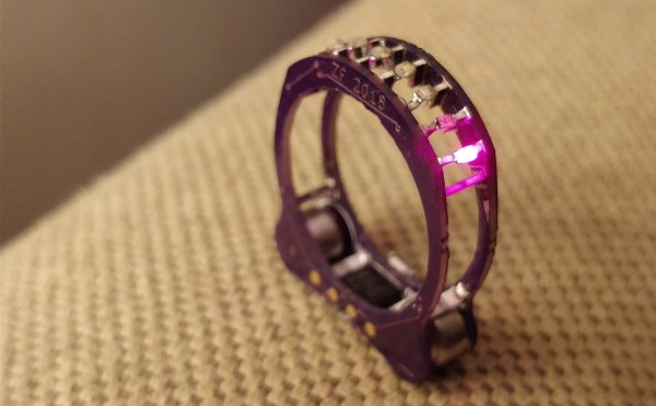
When the cabal of electronic design gurus that pull the invisible strings of the hardware world get together, we imagine they have to show this ring to prove their identity. This is the work of [Zach Fredin], and you’re going to be shocked by the construction and execution of what he calls Cyborg Ring.

The most obvious feature of the Cyborg Ring is the collection of addressable LEDs that occupy the area where gems would be found on a ring. What might not be so obvious is that this is constructed completely of electronic components, and doesn’t use any traditional mechanical parts like standoffs. Quite literally, the surface mount devices are structural in this ring.

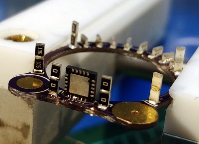
They are also electrical. Here you can see a detail of how [Zach] pulled this off. We are looking at the underside of the ring, the part that goes below your knuckle. One of the two PCBs that are sized to fit your finger has been placed in a Stick Vise while the QFN processor is soldered on end, and the pairs of SMD resistors are put in place.

The precise measurements of each part make it possible to choose components that will perfectly span the gap between the two boards. In the background of the image you can see SMD resistors on their long ends — a technique he used to allow the LEDs themselves to span between one resistor on each of the two PDBs to complete the circuit. Incredible, right?

But it gets better. [Zach] ended up with a working prototype, but has continued to forge ahead with new design iterations. These updates are a delight to read! Make sure you follow his project and check in regularly; if you’ve already looked at this now’s the time to go back and see the new work. The gold pads for the minuscule coin cells which power the ring are being reselected as the batteries didn’t fit well on the original. Some layout problems are being tweaked. And the new spin of boards should be back from fab in a week or so.

Don’t miss the demo video found below. We really like seeing projects that build within the wearble ring form factor. It’s an impressive constraint which [Zach] seems to have mastered. Another favorite of ours is [Kevin’s] Arduboy ring.

Continue reading “Membership Ring Of The Electronic Illuminati”

Retrotechtacular: Tinkertoy And Cordwood In The Pre-IC Era

It is widely accepted that Gutenberg’s printing press revolutionized thought in Europe and transformed the Western world. Prior to the printing press, books were rare and expensive and not generally accessible. Printing made all types of written material inexpensive and plentiful. You may not think about it, but printing–or, at least, printing-like processes–revolutionized electronics just as much.

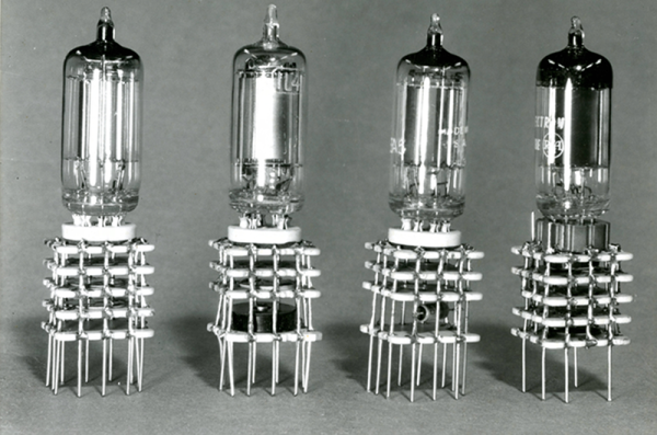
In particular, the way electronics are built and the components we use have changed a lot since the early 1900s when the vacuum tube made amplification possible. Of course, the components themselves are different. Outside of some specialty and enthusiast items, we don’t use many tubes anymore. But even more dramatic has been how we build and package devices. Just like books, the key to lowering cost and raising availability is mass production. But mass producing electronic devices wasn’t always as easy as it is today.

Continue reading “Retrotechtacular: Tinkertoy And Cordwood In The Pre-IC Era”

A Mountain Of Prizes For Projects Using These Parts

Here’s your chance to bring some great stuff home from The Hackaday Prize. For the next 3 weeks we’ll be looking for the best entries using Atmel, Freescale, Microchip, and Texas Instruments parts.

Each of the four contests (yes, four running concurrently) will award the top 50 projects. That’s 200 in total being recognized. The odds are really in your favor — currently some of those lists have less than 50 projects on them — so enter yours right away! Scroll down to see the mountain of prizes that we have for this epic run.

Make Sure We Know About Your Entry

There are two things you need to do to be eligible for this pile of awesome stuff:

  1. Enter your project in the 2015 Hackaday Prize
  2. Leave a comment here with a link to your project and we’ll add it to the list

Do this by the morning of Monday, June 29th to make sure you’re in the running. We’ve been diligent about adding entries to the lists for Atmel, Freescale, Microchip, and Texas Instruments but at the rate new entries have been coming in it’s easy to miss one here or there. Don’t be bashful about asking to be added to these lists!

The prerequisite is to be using a part from one of these four manufacturers. We’ll be looking at these lists for projects using great ideas which have also been well-documented. Tells us why you’re building it, what it does, how you came up with the idea… you know, the whole story!

The Loot

Up for grabs in each of the 4 contests are:

3x Mooshimeters which is a multimeter that uses your smartphone as a wireless readout.

2x DS Logic analyzers which [Adam] reviewed a few weeks back.

15x Stickvise to hold your PCBs (and other things) in place while you work

A continuation of what we’re giving away in each of the 4 contests:

10x Bluefruit LE Sniffers to help you figure out what’s being transmitted by your BTLE devices

10x Cordwood Puzzles; grab your iron and tackle this head-scratching soldering challenge

10x TV-B-Gone is an iconic invention from [Mitch Altman]; one button turns off all TVs


The 2015 Hackaday Prize is sponsored by: