Matchbox Transceiver Pushes The Spy Radio Concept To Its Limits

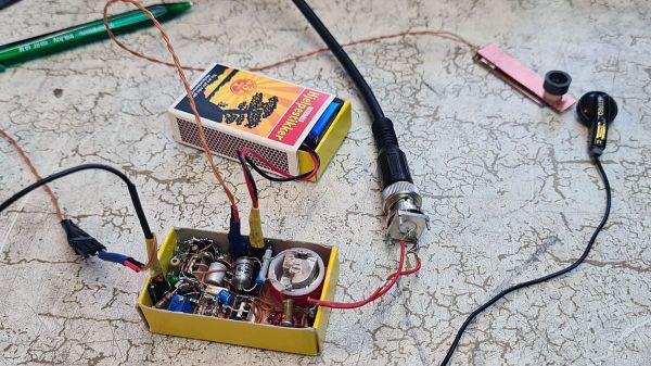
The Altoids tin has long been the enclosure of choice for those seeking to show off their miniaturization chops. This is especially true for amateur radio homebrewers — you really have to know what you’re doing to stuff a complete radio in a tiny tin. But when you can build an entire 80-meter transceiver in a matchbox, that’s a whole other level of DIY prowess.

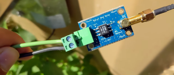
It’s no surprise that this one comes to us from [Helge Fykse (LA6NCA)], who has used the aforementioned Altoids tin to build an impressive range of “spy radios” in both vacuum tube and solid-state versions. He wisely chose solid-state for the matchbox version of the transceiver, using just three transistors and a dual op-amp in a DIP-8 package. There’s also an RF mixer in an SMD package; [Helge] doesn’t specify the parts, but it looks like it might be from Mini-Circuits. Everything is mounted dead bug style on tiny pieces of copper-clad board that get soldered to a board just the right size to fit in a matchbox.

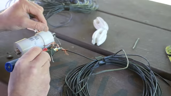
A 9 volt battery, riding in a separate matchbox, powers the rig. As do the earbud and tiny Morse key. That doesn’t detract from the build at all, and neither does the fact that the half-wave dipole antenna is disguised as a roll of fishing line. [Helge]’s demo of the radio is impressive too. The antenna is set up very low to the ground to take advantage of near vertical incidence skywave (NVIS) propagation, which tends to direct signals straight up into the ionosphere and scatter them almost directly back down. This allows for medium-range contacts like [Helge]’s 239 km contact in the video below.

Banging out Morse with no sidetone was a challenge, but it’s a small price to pay for such a cool build. We’re not sure how much smaller [Helge] can go, but we’re eager to see him try.

Continue reading “Matchbox Transceiver Pushes The Spy Radio Concept To Its Limits”

A Practical Guide To Understanding How Radios Work

How may radios do you own? Forget the AM/FM, GMRS/FRS radios you listen to or communicate with. We’re talking about the multiple radios and antennas in your phone, your TV, your car, your garage door opener, every computing device you own- you get the idea. It’s doubtful that you can accurately count them even in your own home. But what principles of the electromagnetic spectrum allow radio to work, and how do antenna design, modulation, and mixing affect it? [Michał Zalewski] aka [lcamtuf] aims to inform you with his excellent article Radios, how do they work?

A simple illustration compares a capacitor to a dipole antenna.

For those of you with a penchant for difficult maths, there’s some good old formulae published in the article that’ll help you understand the physics of radio. For the rest of us, there are a plethora of fantastic illustrations showing some of the less obvious principals, such as why a longer diploe is more directional than a shorter dipole.

The article opens with a thought experiment, explaining how two dipole antennas are like capacitors, but then also explains how they are different, and why a 1/4 wave dipole saves the day. Of course it doesn’t stop there. [lcamtuf]’s animations show the action of a sine wave on a 1/4 wave dipole, bringing a nearly imaginary concept right into the real world, helping us visualize one of the most basic concepts of radio.

Now that you’re got a basic understanding of how radios work, why not Listen to Jupiter with your own homebrew receiver?

Wok Your Way To The Center Of The Galaxy

The round bottom of a proper wok is the key to a decent stir fry, but it also makes it hard to use on traditional Western stoves. That’s why many woks end up in a dark kitchen cabinet, unused and unloved. But wait; it turns out that the round bottom of a wok is the perfect shape for gathering something else — radio waves, specifically the 21-cm neutral hydrogen emissions coming from the heart of our galaxy.

Turning a wok into an entry-level radio telescope doesn’t appear to be all that hard, at least judging by what [Leo W.H. Fung] et al detail in their paper (PDF) on “WTH” or “Wok the Hydrogen.” Aside from the wok, which serves as the main reflector, you’ll need a bit of coaxial cable and some stiff copper wire to fashion a small dipole antenna and balun, plus some plastic tubing to support it at the focal point of the reflector. Measuring the wok’s shape and size, which in turn determines its focal point, is probably the hardest part of the build; luckily, the paper includes tips on doing just that. The authors address the controversy of parabolic versus spherical reflectors and arrive at the conclusion that for a radio telescope fashioned from a wok, it just doesn’t matter.

As for the signal processing chain, WTH holds few surprises. A Nooelec Sawbird+ H1 acts as preamp and filter for the 1420-MHz hydrogen line signal, which feeds into an RTL-SDR dongle. Careful attention is paid to proper grounding and shielding to keep the noise floor as low as possible. Mounting the antenna is a decidedly ad hoc affair, and aiming is as simple as eyeballing various stars near the center of the galactic plane — no need to complicate things.

Performance is pretty good: WTH measured the recession velocity of neutral hydrogen to within 20 km/s, which isn’t bad for something cobbled together from scrap. We’ve seen plenty of DIY hydrogen line observatories before, but WTH probably wins the “get on the air tonight” award.

Thanks to [Heinz-Bernd Eggenstein] for the tip.

The Dipole Antenna Isn’t As Simple As It Appears

Dipole antennas are easy, right? Just follow the formula, cut two pieces of wire, attach your feedline, and you’re on the air.  But then again, maybe not. You’re always advised to cut the legs a little long so you can trim to the right length, but why? Shouldn’t the math just be right? And what difference does wire choice make on the antenna’s characteristics? The simple dipole isn’t really that simple at all.

If you’ve got antenna questions, check out [FesZ]’s new video on resonant dipoles, which is a deep dive into some of the mysteries of the humble dipole. In true [FesZ] fashion, he starts with simulations of various dipole configurations ranging from the ideal case — a lossless conductor in free space with as close to zero diameter conductors as the MMANA antenna simulator can support — and gradually build up to more practical designs. Continue reading “The Dipole Antenna Isn’t As Simple As It Appears”

A Cheap Dipole Antenna From An Extension Cord

Dipoles are a classic builder’s antenna, after all they are usually little more than two pieces of wire and a feedline. But as [Rob] shows us in the video below, there are a few things to consider.

The first thing is where to get the wire. A damaged extension cord donated the wire. That’s actually an interesting idea because you get multiple wires the same length inside the extension cord.  Continue reading “A Cheap Dipole Antenna From An Extension Cord”

Capstan Winch Central To This All-Band Adjustable Dipole Antenna

The perfect antenna is the holy grail of amateur radio. But antenna tuning is a game of inches, and since the optimum length of an antenna depends on the frequency it’s used on, the mere act of spinning the dial means that every antenna design is a compromise. Or perhaps not, if you build this infinitely adjustable capstan-winch dipole antenna.

Dipoles are generally built to resonate around the center frequency of one band, and with allocations ranging almost from “DC to daylight”, hams often end up with a forest of dipoles. [AD0MZ]’s adjustable dipole solves that problem, making the antenna usable from the 80-meter band down to 10 meters. To accomplish this feat it uses something familiar to any sailor: a capstan winch.

The feedpoint of the antenna contains a pair of 3D-printed drums, each wound with a loop of tinned 18-gauge antenna wire attached to some Dacron cord. These make up the adjustable-length elements of the antenna, which are strung through pulleys suspended in trees about 40 meters apart. Inside the feedpoint enclosure are brushes from an electric drill to connect the elements to a 1:1 balun and a stepper motor to run the winch. As the wire pays out of one spool, the Dacron cord is taken up by the other; the same thing happens on the other side of the antenna, resulting in a balanced configuration.

We think this is a really clever design that should make many a ham happy across the bands. We even see how this could be adapted to other antenna configurations, like the end-fed halfwave we recently featured in our “$50 Ham” series.

Dipole Antenna Is Off Balance

A dipole antenna is easy, right? Two wires, each a quarter wavelength long, emanate from a coax or other feedline. Unless it is an off-center dipole. The length is still the same, but you move the feed point to a different part. [KB9VBR] explains how this changes the antenna’s impedance from the nominal 70 ohms of a standard dipole.

Why would you want to do that? The trick is to find a feed point that has acceptable impedance on multiple ham radio bands. Most automatic tuners can handle a certain range of mismatch so using an antenna like this with a tuner can allow one antenna to serve multiple bands with no traps or switches.

Continue reading “Dipole Antenna Is Off Balance”