Werewolf Ears With A Sense For Danger

When walking down a dark street, it’s common to get a sense that one is being followed. It pays to check, of course, but what if we could get better data than simply a vague feeling from the unknown? [caitlinsdad] built a project that can do just that, with a cute pair of ears to boot.

The werewolf ears claim to be ISO Standard, though we’re yet to see the relevant documents to bear that out. Regardless, they use an Adafruit Gemma M0 microcontroller to run the show, hooked up to an infrared proximity sensor to detect movement. When triggered, the Gemma responds to the signal by twitching the wolf ears attached to a headband, alerting the wearer that someone is closing in.

Built and calibrated properly, this could be a useful invention for those who regularly find themselves followed by those skulking on the sidewalk and for whom moving to another neighbourhood is a more expensive option. We’ve seen other responsive wearables, too. Video after the break.

Continue reading “Werewolf Ears With A Sense For Danger”

Dummy Security Camera Is Smarter Than It Looks

The idea behind a dummy security camera is that people who are up to no good might think twice about doing anything to your property when they think they’re being recorded. Obviously a real security camera would be even better, but sometimes that’s just not economically or logistically possible. Admittedly they’re not always very convincing, but for a few bucks, hopefully it’s enough to make the bad guys think twice.

But what if that “fake” camera could do a little more than just look pretty up on the wall? [Chris Chimienti] thought he could improve the idea by adding some electronics that would notify him if motion was detected. As an added bonus, any would-be criminals who might be emboldened by the realization the camera itself is fake might find themselves in for a rude surprise when the notifications start firing off.

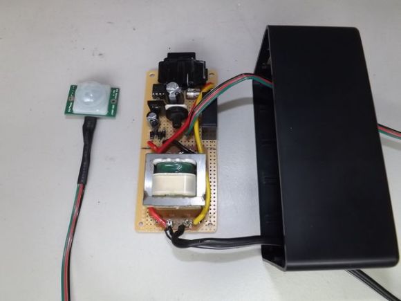
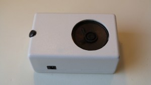
In the video after the break, [Chris] really takes his time walking the viewer through the disassembly of the dummy camera. As it turns out, these things look like they’d make excellent project enclosures; they come apart easily, have nothing but empty space inside, and even have an integrated battery compartment. That alone could be a useful tip to file away for the future.

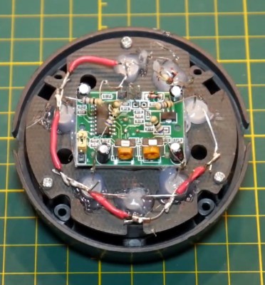
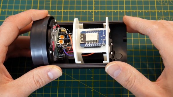
He then goes on to explain how he added some smarts to this dummy camera. Up where the original “lens” was, he installed a PIR sensor, some white LEDs, a light sensor, and the original blinking red LED. All of this was mounted to a very slick 3D printed plate which integrates into the camera’s body perfectly. The new hardware is connected up to a similarly well mounted Wemos D1 Mini inside the camera. The rest of the video goes through every aspect of the software setup, which is sure to be of interest to anyone who’s ever thought of rolling their own IoT device.

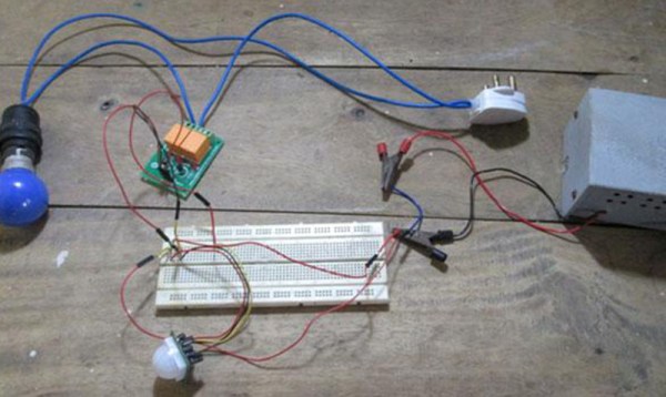
This type of PIR sensor is hacker favorite, and we’ve seen a number of projects using them for all sorts of creative purposes. We’ve even seen them paired with the ESP8266 before for Internet-connected motion sensing, albeit without the tidy security camera enclosure.

Continue reading “Dummy Security Camera Is Smarter Than It Looks”

Flux Capacitor Prop With Christopher Lloyd’s Stamp Of Approval

We love our props here at Hackaday, and whenever we come across a piece from the Back To The Future fandom, it’s hard to resist showcasing it. In this case, [Xyster101] is showing of his build of Doc Brown’s Flux Capacitor.

[Xyster101] opted for a plywood case — much more economical than the $125 it would have cost him for a proper electrical box. Inside, there’s some clever workarounds to make this look as close as possible to the original. Acrylic rods and spheres were shaped and glued together to replicate the trinity of glass tubes, 3/4″ plywood cut by a hole saw mimicked the solenoids, steel rods were sanded down for the trio of points in the centre of the device and the spark plug wires and banana connectors aren’t functional, but complete the look. Including paint, soldering and copious use of hot glue to hold everything in place, the build phase took about thirty hours.

The LEDs have multiple modes, controlled by DIP switches hidden under a pipe on the side of the box. There’s also motion sensor on the bottom of the case that triggers the LEDs to flicker when you walk by. And, if you want to take your time-travel to-go, there’s a nine volt plug to let you show it off wherever — or whenever — you’re traveling to. Check out the build video after the break.

Continue reading “Flux Capacitor Prop With Christopher Lloyd’s Stamp Of Approval”

Evaluating The Unusual And Innovative Perf+ Protoboard

Back in 2015 [Ben Wang] attempted to re-invent the protoboard with the Perf+. Not long afterward, some improvements (more convenient hole size and better solder mask among others) yielded an updated version which I purchased. It’s an interesting concept and after making my first board with it here are my thoughts on what it does well, what it’s like to use, and what place it might have in a workshop.

Perf+ Overview

One side of a Perf+ 2 board. Each hole can selectively connect to bus next to it with a solder bridge. The bus strips are horizontal on the back side.
One side of a Perf+ board. Each hole can selectively connect to the bus next to it with a solder bridge. These bus strips are vertical. The ones on the back are horizontal.

The Perf+ is two-sided perfboard with a twist. In the image to the left, each column of individual holes has a bus running alongside. Each hole can selectively connect to its adjacent bus via a solder bridge. These bus traces are independent of each other and run vertically on the side shown, and horizontally on the back.

Each individual hole is therefore isolated by default but can be connected to one, both, or neither of the bus traces on either side of the board. Since these traces run vertically on one side and horizontally on the other, any hole on the board can be connected to any other hole on the board with as few as two solder bridges and without a single jumper wire.

It’s an innovative idea, but is it a reasonable replacement for perfboard or busboard? I found out by using it to assemble a simple prototype.

Continue reading “Evaluating The Unusual And Innovative Perf+ Protoboard”

Motion Light In Dark Stairwell Brightens Trips To The Basement

WARNNG: Walking around in the dark could be dangerous to your health! You may bump into something or worse, take a tumble down the stairs. Safety conscious [Ganesh] has come up with a solution for us folks too lazy to manually turn on a light. It’s a simple light controlled by a motion sensor that anyone can put together.

The meat and potatoes of the build is an off-the-shelf motion sensor, the same kind that is used in a home security system. We humans emit infrared energy and that is just what this sensor ‘sees’. The motion sensor is powered by 12 VDC and has a pair of DC output leads that are used to control a relay. [Ganesh] used an standard hobby relay board with built in power spike protection diode and transistor to supply the current required to trip the relay. Closing the relay sends mains power to the AC light bulb. Both the triggering threshold and the ‘on’ time are controlled by potentiometers integrated with the motion sensor.

Check the video out after the break of the device working its magic and lighting the way to [Ganesh’s] basement dungeon…

Continue reading “Motion Light In Dark Stairwell Brightens Trips To The Basement”

A Pair Of Projects To Scare The Trick-or-Treaters

The countdown is on! There’s only a few days left until Halloween, and if you’re still looking for something to spice up the experience for the kids heading to your door, [MagicWolfi] has just what you need. He’s put together two motion-sensing projects that are sure to startle any trick-or-treater.

The first project is a chain of LED-lit pumpkins that are activated by a motion sensor. A set of inverters paired with RC delay lines light up the pumpkins sequentially. They are arranged almost like a strand of Christmas lights and are powered by AA batteries, so in theory they could be expanded to make a strand as long as needed. The project was inspired by a motion-sensing dress and works pretty well as a Halloween decoration!

9378581414283863206
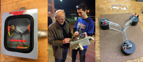
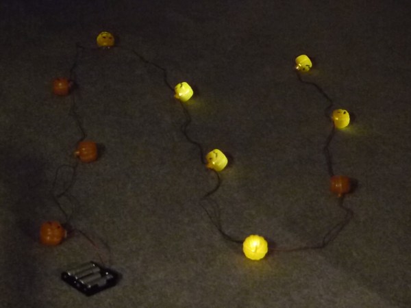
[MagicWolfi] is pairing the LED pumpkins with his second project which uses another motion sensor to play scary sound effects. Dubbed the Scare-o-Matic, this device uses a 45-millimeter speaker connected to a SparkFun microSD audio module to produce the scary sound effects. Each time it is triggered it plays a different sound from the list. There are videos and schematics for each of these projects on the project sites if you are interested in recreating any of these before Friday!

A Motion Activated AC Switching Circuit Using Mostly Discrete Components

AC motion switch

If you’ve ever dealt with a brightly lit Christmas tree, you might understand the frustration of having to crawl underneath the tree to turn the lights on and off. [brmarcum] feel’s your pain. He’s developed his own motion activated AC switching circuit to turn the lights on and off automatically. A motion sensor ensures that the lights are only on when there are people around to actually see the lights. The circuit also has an adjustable timer so [brmarcum] can change the length of time that the lights stay on.

The project is split into several different pieces. This makes the building and debugging of the circuit easier. The mains power is first run through a transformer to lower the voltage by a factor of 10. What remains is then filtered and regulated to 9VDC. [brmarcum] is using a Parallax PIR sensor which requires 4.5V. Therefore, the 9V signal is then lowered once more using a voltage divider circuit.

When the PIR sensor is triggered, it activates the timer circuit. The timer circuit is driven by a 555 timer. The circuit itself was originally borrowed from a classic Forrest Mims book, though it was slightly modified to accommodate the PIR sensor. The original push-button trigger was removed and replaced with the signal from the PIR sensor. The only problem is that the circuit was expecting a low signal as the trigger and the PIR sensor outputs a high signal. [brmarcum] resolved this problem with an NPN BJT to invert the signal. Once the timer is triggered, it flips on a relay that allows the mains electricity to flow through to the lights.

[brmarcum] soldered the entire circuit onto a piece of protoboard. The final product was then mounted securely inside of an insulated plastic case. This allows him to mount the circuit safely underneath the Christmas tree skirt. The PIR sensor is kept external to the enclosure and wired up into the tree itself. This allows the sensor to still detect motion in the room while the rest of the circuit is hidden away.

[via Reddit]