UV Laser Projector Shines With Glow-in-the-Dark Vinyl

Mirror galvanometers were originally developed in the 17th century to precisely measure very small changes in current. Unlike other instruments of the day, a mirror galvanometer could clearly show minute current variations by translating tiny movements of the mirror into large movements of the light reflected off of the mirror. Before clean electrical amplification became possible, this was the best means of measuring tiny differences in current. True mirror galvanometers are very sensitive instruments, but hobby servos can be used as a low-fidelity alternative, like with this project on Hackaday.io created by [robives].

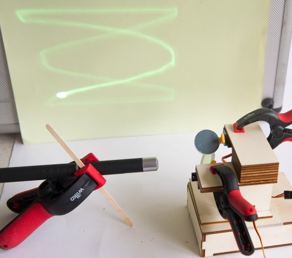
Using a mirror galvanometer is by far the most common technique for laser projection shows – it’s really the only way to move the laser’s beam quickly enough to create the visual illusion of a solid line in real time. A mirror galvanometer works by using coils to attract magnets attached to the mirror, allowing the angle of the mirror to change when current is applied to the coils. This movement is extremely small, but is amplified by the distance to the projection surface, meaning the laser’s beam can move huge distances in an instance. If you’ve ever seen a laser show, it almost certainly used this technique. But driving galvos requires a beefy DAC, so we can’t blame [robives] for wanting to keep it digital.

[robives’s] project side-steps the need for galvanometers by using glow-in-the-dark vinyl and a UV laser. The result is a laser beam trail which lasts much longer, which means that solid lines are visible without the need for high-speed galvos. A build like this lets you experiment with laser projections without dealing with sensitive mirror galvos, and instead use components that you probably already have sitting on your workbench.

Continue reading “UV Laser Projector Shines With Glow-in-the-Dark Vinyl”

Shedding Light On The Mechanics Of Film Projection

Do you know how a film projector works? We thought we did, but [Bill Hammack] made us think twice. We have covered the Engineer Guy’s  incredibly informative videos many times in the past, and for good reason. He not only has a knack for clear explanation, the dulcet tones of his delivery are hypnotically soothing. In [Bill]’s latest video, he tears down a 1979 Bell & Howell 16mm projector to probe its inner workings.

Movies operate on the persistence of vision (POV) principle, which basically states that the human brain creates the illusion of motion from still images. If you’ve ever drawn circles and figure eights in the nighttime air with a sparkler or perused a flip book, then you’ve experimented with POV.

A film projector is no different in theory. Still images on a strip of celluloid are passed between a lamp and a lens, which project the images on to a screen. A device called a shuttle advances the film by engaging its teeth into the holes on the edge of the film and moving downward, pulling the film with it. The shuttle then disengages its teeth and moves up and forward, starting the process again.

shutters
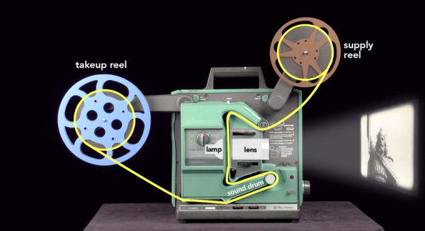
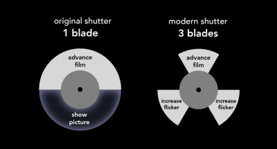
Film is projected at a rate of 24 frames per second, which is sufficient to create the POV illusion. A projector’s shutter inserts itself between the lamp and the lens, blocking the light to prevent projection of the film’s physical movement. But these short periods of darkness, or flicker, present a problem. Originally, shutters were made in the shape of a semi-circle, so they block the light half of the time. Someone figured out that increasing the flicker rate to 60-70 times per second would have the effect of constant brightness. And so the modern shutter has three blades: one blocks projection of the film’s movement, and the other two simply increase flicker.

[Bill] explains how the projector reads the optical soundtrack. He also delves into the mechanisms that allow continuous sound playback alongside intermittent projection of the image frames. You’ll never look at a projector the same way again.

Want to know more about optical soundtracks? Check out this Retrotechtacular that explores the subject in detail.

Continue reading “Shedding Light On The Mechanics Of Film Projection”

Caption CERN Contest – Tabletop Projection

Week 17 of the Caption Cern Contest on Hackaday.io is now a polished sheet metal memory, but the captions live on! Thanks to everyone who entered. We may never know exactly what these scientists and their ladder holding friend were up to. We do know a bit more about some of the equipment in that photo though! Astute reader [Pierlu] dropped a photo comment here on the Blog showing some interesting lawn ornaments over at CERN. The device to the right looks quite a bit like the device on the right side of our original image. We don’t have a close-up to be sure, but chances are this is part of a Cockcroft–Walton generator.

The Funnies:

  • “…and six cute little kittens, too. I wonder how she got in here? Hey, hold that ladder steady, Schrödinger!” – [sbi.gaijin]
  • “Good news: the shrink ray worked. Bad news: we have to escape the janitor’s vacuum cleaner” – [Cody]
  • “Archeology Professor Ammit Duat from the University of Cairo, assisting CERN engineer Jack Orsiris in changing the locks on the door to the Egyptian underworld” – [carbonfiber]

This week’s winner is [alj5432] with “Sticking with CERN’s usual “Go Big or Go Home” theme,
scientists make adjustments to LHC’s massive “Press To Start” Button.” We’re sure [alj5432] will enjoy probing digital circuits with his new Logic Pirate From The Hackaday Store! Congratulations [alj5432]!

Week 18

CEcern-18-sm
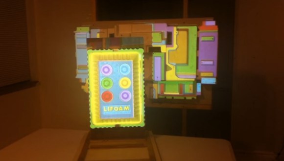
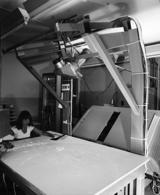
RN is no stranger to innovative display systems. That should be no surprise, considering CERN staff are trying to work with massive amounts of data collected by thousands of scientists. Here we see one of those systems, a projection table of some sort.

Today video projectors are relatively cheap and easy to make, thanks to advances in LCD and MEMS technology. Back when this image was shot in 1979 though, video projectors were expensive and rare commodities. What was this scientist doing?

You tell us!

Once again, we’re giving away a Logic Pirate from The Hackaday Store.

Add your humorous caption as a comment to this project log. Make sure you’re commenting on the contest log, not on the contest itself.

As always, if you actually have information about the image or the people in it, let CERN know on the original image discussion page.

Good Luck!

Direction Projection Is A Beacon In The Night

Navigating with your phone can be a hassle: the phone displays a tiny map that you’re never supposed to look at while driving, but of course you do. [Mikeasaurus] has the ultimate solution: Direction Projection! Mike has created an augmented reality system with no glass heads-up display, and no goggles ala Microsoft Hololens. The road ahead is his canvas. A standard projector mounted atop his car displays maps and turn indicators, all from his phone. Linking the phone and projection system would normally involve HDMI or analog video cables strung through the roof. [Mikeasaurus] simplifies that by using a Chromecast, which allows him to stream his phone’s screen over WiFi.

rooftop2
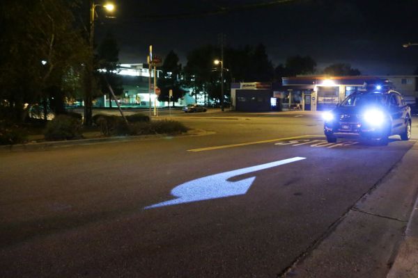
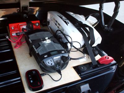
The projector itself is the HD25-LV, a 3500 Lumen model from Optima. the HD25-LV is capable of 1080p, though in this situation, brightness is much more important than resolution. [Mikeasaurus] mounted the projector along with a gel cell battery and 900 watt DC to AC  inverter to power it. A mobile WiFi hotspot fills out the rooftop kit. Leaving an expensive setup like that on top of a car is a recipe for disaster – be it from rain, rocks, or theft. [Mikeasaurus] thought ahead and strapped his setup down inside a roof mounted cargo box. A plastic covered hole in the front of the box allows the projector to shoot down on the road while protecting its lens. We’d want to add a vent and fan to ensure that projector gets a bit of airflow as well.

On the road, the system actually works. Understandably, it’s not going to work very well during the day, but at night the system really shines! Just don’t tailgate – you wouldn’t want the driver in front of you to know exactly where you’re going, would you?

Continue reading “Direction Projection Is A Beacon In The Night”

hologram

Dead Simple Hologram Effect

We’ve all seen holograms in movies, and occasionally we see various versions of the effect in real life. The idea of having a fully three-dimensional image projected magically into space is appealing, but we haven’t quite mastered it yet. [Steven] hasn’t let that stop him, though. He’s built himself a very simple device to display a sort of hologram.

His display relies on reflections. The core of the unit is a normal flat screen LCD monitor laid on its back. The other component looks like a four-sided pyramid with the top cut off. The pyramid is made from clear plastic transparency sheets, held together with scotch tape. It’s placed on top of the LCD with the narrow end facing down.

[Steven] then used the open source Blender program to design a few 3D animations. Examples include a pterodactyl flying and an approximation of the classic Princess Leia hologram from Star Wars Episode 4. The LCD screen displays the animation from four different angles at once. The images are displayed up and onto the transparency sheet, which then get reflected to your eyes. The result is an image that looks almost as if it’s floating in space if viewed from the proper angle. If you move around the screen you can see the image from all four sides, which helps to sell the effect. Not bad for a few dollars worth of parts. Continue reading “Dead Simple Hologram Effect”

TightLight: A 3D Projection Mapping Assistant

tightLight

Anyone can grab a projector, plug it in, and fire a movie at the wall. If, however, you want to add some depth to your work–both metaphorical and physical–you’d better start projection mapping. Intricate surfaces like these slabs of styrofoam are excellent candidates for a stunning display, but not without introducing additional complexity to your setup. [Grady] hopes to alleviate some tedium with the TightLight (Warning: “music”).

The video shows the entire mapping process of which the Arduino plays a specific role toward the end. Before tackling any projector calibration, [Grady] needs an accurate 3D model of the projection surface, and boy does it look complicated. Good thing he has a NextEngine 3D laser scanner, which you’ll see lighting the surface red as it cruises along.

Enter the TightLight: essentially 20 CdS photocells hooked up to a Duemilanove, each of which is placed at a previously-marked point on the 3D surface. A quick calibration scan scrolls light from the projector across the X then Y axis, hitting each sensor to determine its exact position. [Grady] then merges the photocell location data with the earlier 3D model using the TouchDesigner platform, and bam: everything lines up and plays nice.

A Fifty-dollar Projection Screen You Can Be Proud Of

[Lou] wrote in to share the fifty-dollar projection screen he built in his home. We’ve seen several of these projects lately. Unlike the one used at a lake cabin, or the other that fills an awkward alcove, this version doesn’t use fabric for the screen. He actually painted it right on the wall.

The key to achieving a great end product is to make sure your wall is flat. [Lou’s] instructional video (embedded after the break) shows how to patch holes in the wall, and repair high spots. Before beginning the process he uses his projector’s grid feature to map out the portion of the wall that will be used as a viewing area (that’s the grid seen on the screen above). Once the area has been marked with masking tape and carefully repaired he paints it with bright white or silver paint. You might also consider a paint additive for better results. We’ve seen sand blasting beads used for this purpose.

A frame is added to the area to make it look like a proper screen. This is nothing more than molding covered in black fabric. [Lou] stretches the fabric around the molding, using duct tape to hold it in place until it can be stapled down.

Continue reading “A Fifty-dollar Projection Screen You Can Be Proud Of”