Logic Analyzers: Capabilities And Limitations

Last time, we’ve used a logic analyzer to investigate the ID_SD and ID_SC pins on a Raspberry Pi, which turned out to be regular I2C, and then we hacked hotplug into the Raspberry Pi camera code with an external MCU. Such an exercise makes logic analyzers look easy, and that’s because they are! If you have a logic analyzer, you’ll find that a whole bunch of hacks become available to you.

In this article, let’s figure out places where you can use a logic analyzer, and places where you can’t. We’ll start with the first limitation of logic analyzers – capture speed. For instance, here’s a cool thing you can buy on Aliexpress – a wristband from TTGO that looks like a usual fitness tracker, but has an ESP32 in it, together with an IMU, an RTC, and an IPS screen! The seller also has an FFC-connectable devboard for programming this wristband over UART, plus vibromotor and heartrate sensor expansion modules.

You can run C, MicroPython, Rust, JavaScript, or whatever else – just remember to bring your own power saving, because the battery is super small. I intended to run MicroPython on it, however, and have stumbled upon a problem – the ST7735-controller display just wouldn’t work with the st7735.py library I found; my image would be misaligned and inverted.

The specifications didn’t provide much other than “ST7735, 80×160”. Recap – the original code uses an Arduino (C++) ST7735 library and works well, and we have a MicroPython ST7735 library that doesn’t. In addition to that, I was having trouble getting a generic Arduino ST7735 library to work, too. Usually, such a problem is caused by the initialization commands being slightly different, and the reason for that is simple – ST7735 is just the name of the controller IC used on the LCD panel.

Each display in existence has specifics that go beyond the controller – the pixels of the panel could be wired up to the controller in a bunch of different ways, with varying offsets and connection types, and the panel might need different LCD charge pump requirements – say, depending on the panel’s properties, you might need to write 0x10 into a certain register of the ST7735, or you will need 0x40. Get one or more of these registers wrong, and you’ll end up with a misaligned image on your display at best, or no output at worst. Continue reading “Logic Analyzers: Capabilities And Limitations”

Diving Into Starlink’s User Terminal Firmware

The average Starlink user probably doesn’t spend a lot of time thinking about their hardware after getting the dish aligned and wiring run. To security researchers, however, it’s another fascinating device to tinker with as they reverse-engineer the firmware and try to both find out what makes it tick, as well as how to break it. This is essentially the subject of [Carlo Ramponi]’s article over at Quarkslab as he digs into the firmware architecture and potential weaknesses in its internal communication.

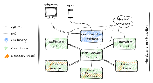
The user terminal hardware itself is a quite standard AArch64 ARM-based SoC, along with the proprietary communication interface, all of which is controlled by the Linux-based firmware. Dumping the firmware itself was made easy thanks to existing work by researchers at the KU Leuven, involving dumping the contents of the onboard eMMC storage. After this the firmware architecture could be analyzed, which turned out to consist out of mostly C++-based binaries, but with a single big binary for the user front-end written in Go.

Communication between these processes is handled through a custom inter-process protocol called ‘Slate Sharing’, all of which is coordinated via the core User Terminal Control process. It are these Slate IPC messages which form the most likely attack surface for a fuzzing attack, with the SoftwareUpdateRequest command being an interesting target as it would seem to not require authentication since it doesn’t address a specific user. This work is part of [Carlo]’s master’s thesis, and should form the basis of further research on the Starlink User Terminal firmware.

DisplayPort: Tapping The Altmode

Really, the most modern implementation of DisplayPort is the USB-C DisplayPort altmode, synonymous with “video over USB-C”, and we’d miss out if I were to skip it. Incidentally, our last two articles about talking USB-PD have given a few people a cool new toy to play with – people have commented on the articles, reached out to me for debugging help, and I’ve even seen people build the FUSB302B into their projects! Hot on the heels of that achievement, let’s reach further and conquer one more USB-C feature – one that isn’t yet openly available for us to hack on, even though it deserves to be.

For our long-time readers, it’s no surprise to see mundane capabilities denied to hackers. By now, we all know that many laptops and phones let you get a DisplayPort connection out of a USB-C port. Given that the USB-C specifications are openly available, and we’ve previously implemented a PD sink using those specifications, you’d expect that we could do DisplayPort with the same ease. Yet, the DisplayPort altmode specification is behind a VESA membership paywall, with a hefty pricetag – a practice of theirs that has been widely criticized, counter to their purpose as a standards organization and having resulted in some of their standards failing.

Not to worry, however – we can easily find an assortment of PDFs giving a high-level overview and some details of the DisplayPort altmode, and here’s my favorite! I also have a device running MicroPython with a FUSB302 chip connected, and a few DisplayPort altmode devices of mine that I can disassemble. This, turns out, is more than enough for us to reverse-engineer our way into an open-source DisplayPort altmode library!

Continue reading “DisplayPort: Tapping The Altmode”

Closing In On A PC Enabled PSVR2

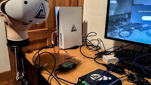
When the PlayStation VR2 headset was released, people wondered whether it would be possible to get the headset to work as a PC VR headset. That would mean being able to plug it into a PC and have it work as a VR headset, instead of it only working on a PS5 as Sony intended.

Enthusiasts were initially skeptical and at times despondent about the prospects, but developer [iVRy]’s efforts recently had a breakthrough. A PC-compatible VR2 is looking more likely to happen.

So far [iVRy] is claiming they have 6 DOF SLAM (Simultaneous Localisation and Mapping), Prox sensor, and stereo camera data.

Most of the juicy bits are paywalled behind [iVRy]’s Patreon.  We’re hoping the jailbreak process will eventually be open-sourced.

The PS VR2 headset is quite unlike a PC VR headset in a number of ways, and it has not been historically easy to work with Sony’s products from a reverse-engineering perspective, whether it’s an attempt to improve the user experience of an annoying headset, or an attempt to understand the not-even-remotely-sanely-designed protocols behind the Sony Memory Stick. Getting the PS VR2 headset to work in a way it wasn’t intended was expected to be an uphill battle.

It’s not a finished job, but judging by the progress regularly shared on [iVRy]’s Twitter account, it might only be a matter of time.

Reverse Engineering Reveals Hidden API In Abandonware Trail Camera

It sometimes seems like there are two kinds of cheap hardware devices: those dependent on proprietary software that is no longer available and those that are equally dependent but haven’t been abandoned just quite yet. But rest assured, abandonment is always on the table, and until then, you get to deal with poorly written apps that often suffer from a crippling lack of essential functionality.

Such was the case for the wireless game camera that [Chris Jones] scored on the cheap, but rather than suffering with the original software, he decided to reverse engineer the camera and turn it into something more useful. The eBay description was promising — Bluetooth LE! WiFi! — but the reality proved less so. To save the batteries, WiFi is off by default and can only be turned on by connecting to the camera via BLE using a janky and crash-prone Android app.

[Chris]’ first step in reverse engineering the camera was to snoop into the BLE by capturing the Bluetooth packets to a file and running them through Wireshark. This revealed a write command with the text “BT_KEY_ON” — very promising. After verifying that this command turned on the camera’s access point, [Chris] got to work capturing WiFi packets using PCAPDroid and analyzing the results, again with Wireshark. Using every function available in the OEM app eventually revealed the full API on the camera, which gives file system control, access to individual images, and even putting the camera into live video mode.

Continue reading “Reverse Engineering Reveals Hidden API In Abandonware Trail Camera”

Sniffing Passwords, Rickrolling Toothbrushes

If you could dump the flash from your smart toothbrush and reverse engineer it, enabling you to play whatever you wanted on the vibrating motor, what would you do? Of course there’s no question: you’d never give up, or let down. Or at least that’s what [Aaron Christophel] did. (Videos, embedded below.)

But that’s just the victory lap. The race began with previous work by [Cyrill Künzi], who figured out that the NFC chip inside was used for a run-time counter, and managed to reset it by sniffing the password with an SDR as it was being transmitted. A great hack to be sure, but it only works for people with their own SDR setup.

With the goal of popularizing toothbrush-head-NFC-hacking, [Aaron] busted open the toothbrush itself, found the debug pins, dumped the flash, and got to reverse engineering. A pass through Ghidra got him to where the toothbrush reads the NFC tag ID from the toothbrush head. But how does it get from the ID to the password? It turns out that it runs a CRC on a device UID from the NFC tag itself and also a manufacturer’s string found in the NFC memory, and scramble-combines the two CRC values.

Sounds complicated, but the NFC UID can be read with a cellphone app, and the manufacturer’s string is also printed right on the toothbrush head itself for your convenience. Armed with these two numbers, you can calculate the password, and convince your toothbrush head that it’s brand new, all from the comfort of your smartphone! Isn’t technology grand?

We’re left guessing a little bit about the Rickroll hack, but we’d guess that once [Aaron] had the debug pins on the toothbrush’s microcontroller, he just couldn’t resist writing and flashing in a custom firmware. Talk about dedication.

[Aaron] has been doing extensive work on e-paper displays, but his recent work on the Sumup payment terminal is a sweet look at hacking into higher security devices with acupuncture needles.

Continue reading “Sniffing Passwords, Rickrolling Toothbrushes”

Tesla Door Phone Decoded (Not That Tesla)

[Danman] has digital door phones manufactured by Tesla — or at least, a Tesla, as they’re not to be confused with the carmaker, though. The problem is if someone comes to the door when no one’s home, there’s no remote indicator. The answer? Reverse engineer the protocol and fix it.

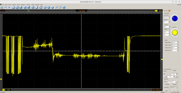
A quick dump on a storage scope showed the data clearly, but it wasn’t obvious what protocol it was using. After a little analysis, it proved the datastream used 4 PWM pulses as symbols with three symbols: one, zero, and stuffing sequence.

Once you can read the bits, it is easy to determine that each frame consists of a 16-bit destination and source address, along with a command byte and a checksum byte. Each station can have an ID from 000 to 999 although you can only dial up to number 323. Some nodes are special, and there are ways to address particular units.

Connecting to the hardware took a transformer for isolation. Honestly, unless you have this exact hardware, this isn’t likely to be something you can directly use. However, it is a great example of how you can figure out a specialized device and bend it to your will.

We love reverse engineering projects. In some cases, it is easier if you have a CT scan.