Pocketable Yagi Antenna Really Shoots For Distance

For amateur radio operators, the quest for the perfect antenna never seems to end. Perhaps that’s because our requirements are always changing. We never quite seem to get to one design that can do everything. This copper-foil Yagi antenna might not do everything, but it really seems to tick off the boxes for gain and directionality along with ultra-portability.

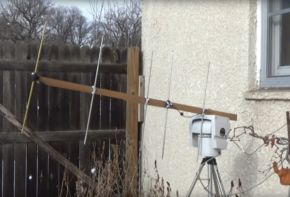
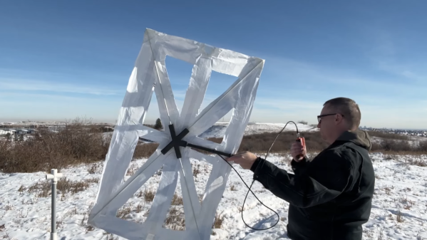
If you’ve been following [Ben Eadie (VE6SFX)]’s trip down the rabbit hole of lightweight antenna building, you’ll recall that he’s already knocked off a J-pole antenna and a stealthy mobile slot antenna using little more than copper foil tape. Both of those designs performed great, but [Ben] had bigger fish to fry: he wanted to build a directional antenna for the 2-meter band and go for distance. The traditional Yagi-Uda is generally the preferred design for beam antennas, but they tend to be bulky and cumbersome. But with a roll of copper foil tape [Ben] was able to lay out a three-element Yagi on a sheet of Tyvek wrap. Reinforced with some packing tape and stiffened with a couple of fiberglass rods attached to a 3D printed handle, and it was ready to go.

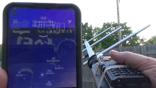
[Ben]’s field test results were most impressive. Not only was he able to open up repeaters up to 90 km away, but he was getting good signal reports to boot. He was even able to reach a repeater 150 km distant, just barely though. Still, that’s mighty impressive performance from something that looks like a Union Jack and rolls up to fit in a pocket.

Continue reading “Pocketable Yagi Antenna Really Shoots For Distance”

Listening To The ISS On The Cheap

Like any hobby, amateur radio has no upper bounds on what you can spend getting geared up. Shacks worth tens of thousands of dollars are easy to come by, and we’ll venture a guess that there are hams out there pushing six figures with their investment in equipment. But hands down, the most expensive amateur radio station ever has to be the one aboard the  International Space Station.

So what do you need to talk to a $100 billion space station? As it turns out, about $60 worth of stuff will do, as [saveitforparts] shows us in the video below. The cross-band repeater on the ISS transmits in the 70-cm ham band, meaning all that’s needed to listen in on the proceedings is a simple “handy talkie” transceiver like the $25-ish Baofeng shown. Tuning it to the 437.800-MHz downlink frequency with even a simple whip antenna should get you some reception when the ISS passes over.

In our experience, the stock Baofeng antenna isn’t up to the job, so something better like the Nagoya shown in the video is needed. Better still is a three-element Yagi tuned down slightly with the help of a NanoVNA; coupled with data on when the ISS will be within line-of-sight, picking up the near-constant stream of retransmissions from the station as Earth-based hams work it should be a snap — even though [saveitforparts] only listened to the downlink frequency here, for just a bit more of an investment it’s also possible for licensed hams to uplink to the ISS on 145.900 MHz.

For those who want a slightly higher level of difficulty, [saveitforparts] also has some tips on automating tracking with an old motorized mount for CCTV cameras. Pitchfork notwithstanding, it’s not the best antenna tracker, but it has promise, and we’re eager to see how it pans out — sorry. But in general, the barrier to entry for getting into space communications is so low that you could easily make this a weekend project. We’ve been discussing this and other projects on the new #ham-shack channel over on the Hackaday Discord. You should pop over there and check it out — we’d be happy to see you there.

Continue reading “Listening To The ISS On The Cheap”

Printing Antennas On Circuit Boards

Yagi-Uda antennas, or simply “Yagis”, are directional antennas that focus radio waves to increase gain, meaning that the radio waves can travel further in that direction for a given transmitter power. Anyone might recognize an old TV antenna on a roof that uses this type of antenna, but they can be used to increase the gain of an antenna at any frequency. This one is designed to operate within the frequencies allotted to WiFi and as a result is so small that the entire antenna can be printed directly on a PCB.

The antenna consists of what is effectively a dipole antenna, sandwiched in between a reflector and three directors. The reflector and directors are passive elements in that they interact with the radio wave to focus it in a specific direction, but the only thing actually powered is the dipole in the middle. It looks almost like a short circuit at first but thanks to the high frequencies involved in this band, will still function like any other dipole antenna would. [IMSAI Guy], who created the video linked above which goes over these details also analyzed the performance of this antenna and found it to be fairly impressive as a WiFi antenna, but he did make a few changes to the board for some other minor improvements in performance.

The creator of these antennas, [WA5VJB] aka [Kent Britain] is an antenna builder based in Texas who has developed a few unique styles of antennas produced in non-traditional ways. Besides this small Yagi, there are other microwave antennas available for direction-finding, some wide-band antennas, and log-periodic antennas that look similar to Yagi antennas but are fundamentally different designs. But if you’re looking to simply extend your home’s WiFi range you might not need any of these, as Yagi antennas for home routers can be a lot simpler than you ever imagined.

Continue reading “Printing Antennas On Circuit Boards”

Hunting For Space Pirates

Ever since the first artificial satellite was launched into orbit, radio operators around the world have been tuning in to their space-based transmissions. Sputnik 1 only sent back pulses of radio waves, but in the decades to follow ever more advanced radio satellites were put into service that could support two-way communications from Earth to space and back again.

Some of these early satellites were somewhat lacking in security, though, and have been re-purposed by various pirates around the world for their own ends. [Gabe] aka [saveitforparts] is here to show us how to hunt for those pirates and listen in on their radio traffic.

Pirates on these satellites have typically used them for illicit activities, and it is still illegal to use them for non-governmental or non-military purposes, so [Gabe] notes that he will only be receiving, not transmitting. The signals he is tuning in to are VHF transmissions, specifically around 220 MHz. That puts them easily within the reach of the RTL-SDR and common ham radio equipment, but since they are coming from space a more directional antenna is needed. [Gabe] quickly builds a Yagi antenna from scrap, tuned specifically to 255 MHz, and mounts it to an old remote-controlled security camera mount which allows him to point it exactly at the satellite and monitor transmissions.

From there he is able to pick up what looks like a few encrypted and/or digital transmissions, plus analog transmissions of likely pirates speaking a language he guesses to be Portuguese. He also hears what he thinks is a foreign TV broadcast, but oddly enough turns out to be NPR. These aren’t the only signals in space to tune to, either. There are plenty of purpose-built ham radio satellites available for any licensed person to use, and we’ve also seen this other RTL-SDR configured to snoop on Starlink signals.

Continue reading “Hunting For Space Pirates”

Retrotechtacular: Measuring TV Audiences With The “Poll-O-Meter”

It may come as a shock to some, but TV used to be a big deal — a very big deal. Sitting down in front of the glowing tube for an evening’s entertainment was pretty much all one had to do after work, and while taking in this content was perhaps not that great for us, it was a goldmine for anyone with the ability to monetize it. And monetize it they did, “they” being the advertisers and marketers who saw the potential of the new medium as it ramped up in early 1950s America.

They faced a bit of a problem, though: proving to their customers exactly how many people they were reaching with their ads. The 1956 film below shows one attempt to answer that question with technology, rather than guesswork. The film features the “Poll-O-Meter System,” a mobile electronic tuning recorder built by the Calbest Electronics Company. Not a lot of technical detail is offered in the film, which appears aimed more at the advertising types, but from a shot of the Poll-O-Meter front panel (at 4:12) and a look at its comically outsized rooftop antenna (12:27), it seems safe to assume that it worked by receiving emissions from the TV set’s local oscillator, which would leak a signal from the TV antenna — perhaps similar to the approach used by the UK’s TV locator vans.

The Poll-O-Meter seems to have supported seven channels; even though there were twelve channels back in the day, licenses were rarely granted for stations on adjacent channels in a given market, so getting a hit on the “2-3” channel would have to be considered in the context of the local market. The Poll-O-Meter had a charming, homebrew look to it, right down to the hand-painted logos and panel lettering. Each channel had an electromechanical totalizing counter, plus a patch panel that looks like it could be used to connect different counters to different channels. There even appears to be a way to subtract counts from a channel, although why that would be necessary is unclear. The whole thing lived in the back of a 1954 VW van, and was driven around neighborhoods turning heads and gathering data about what channels were being watched “without enlisting aid or cooperation of … users.” Or, you know, their consent.

It was a different time, though, which is abundantly clear from watching this film, as well as the bonus ad for Westinghouse TVs at the end. The Poll-O-Meter seems a little silly now, but don’t judge 1956 too hard — after all, our world is regularly prowled by equally intrusive and consent-free Google Street View cars. Still, it’s an interesting glimpse into how one outfit tried to hang a price tag on the eyeballs that were silently taking in the “Vast Wasteland.”

Continue reading “Retrotechtacular: Measuring TV Audiences With The “Poll-O-Meter””

Tracking Satellites With A Commodore PET

A recent writeup by Tom Nardi about using the 6502-based NES to track satellites brought back memories of my senior project at Georgia Tech back in the early 80s.  At our club station W4AQL, I had become interested in Amateur Radio satellites.  It was quite a thrill to hear your signal returning from space, adjusting for Doppler as it speeds overhead, keeping the antennas pointed, all while carrying on a brief conversation with other Earth stations or copying spacecraft telemetry, usually in Morse code.

Continue reading “Tracking Satellites With A Commodore PET”

Lowering The Boom On Yagi Element Isolation

Antenna design can be confusing, to say the least. There’s so much black magic that goes into antennas that newbies often look at designs and are left wondering exactly how the thing could ever work. Slight changes in length or the angle between two elements result in a vastly different resonant frequency or a significant change in the antenna’s impedance. It can drive one to distraction.

Particularly concerning are the frequent appearances of what seem to be dead shorts between the two conductors of a feedline, which [andrew mcneil] explored with a pair of WiFi Yagi antennas. These highly directional antennas have a driven element and a number of parasitic elements, specifically a reflector behind the driven element and one or more directors in front of it. Constructive and destructive interference based on the spacing of the elements and capacitive or inductive coupling based on their length determine the characteristics of the antenna. [Andrew]’s test antennas have their twelve directors either isolated from the boom or shorted together to the shield of the feedline. In side-by-side tests with a known signal source, both antennas performed exactly the same, meaning that if you choose to build a Yagi, you’ve got a lot of flexibility in what materials you choose and how you attach elements to the boom.

If you want to dive a little deeper into how the Yagi works, and to learn why it’s more properly known as the Yagi-Uda antenna, check out our story on their history and operational theory. And hats off to [andrew] for reminding us that antenna design is often an exercise in practicality; after all, an umbrella and some tin cans or even a rusty nail will do under the right circumstances.

Continue reading “Lowering The Boom On Yagi Element Isolation”