Toaster Oven Reflow Soldering Roundup

SMD components have a lot of advantages over the through-hole parts our fathers and grandfathers soldered. Working with these tiny surface mount components requires a larger investment than a soldering iron and a wire-wrap gun, though. Here’s a few reflow ovens that were sent in over the past week or two.

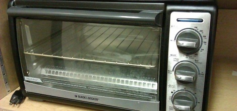
[ramsay] bought a 110 V toaster oven off of eBay. Even though [ramsay] is in England and has 230 V mains, everything in the oven is mechanical and works just fine with a higher voltage. His first test didn’t go quite as planned; the solder paste wasn’t melting at 120° C, so he cranked up the temperature and learned that the FR in FR-4 stands for flame retardant. Never deterred, [ramsay] decided to build a controller so the temperature ramps up and cools off at the right rates for the flux and paste to do their thing.

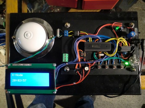
Solder paste has a temperature profile that requires the board to be kept at a temperature between 150° and 180° C for a minute or so before climbing up to 220° for a second so the solder will melt. [Nicolas] had the interesting idea of putting a USB port in his toaster oven and storing the heating profiles on his desktop. The build uses an MSP430 microcontroller to turn the relays powering heating elements on and off. [Nick] is working on a C# desktop app to monitor and regulate the oven temperature from his computer, so we’re fairly interested in seeing the final results.

Watching the SMD self-alignment videos on YouTube is a lot more fun than messing around with tweezers, stereo microscopes, and extremely fine soldering irons. If you’ve got a better idea for a toaster/reflow oven, send it in on our tip line and we’ll check it out.

Glove-based Touch Screen From A CRT Monitor

Here’s a bulky old CRT monitor used as a touch-screen without any alterations. It doesn’t use an overlay, but instead detects position using phototransistors in the fingertips of a glove.

Most LCD-based touch screens use some type overlay, like these resistive sensors. But cathode-ray-tube monitors function in a fundamentally different way from LCD screens, using an electron gun and ring of magnets to direct a beam across the screen. The inside of the screen is coated with phosphors which glow when excited by electrons. This project harness that property, using a photo transistor in both the pointer and middle finger of the glove. An FPGA drives the monitor and reads from the sensors. It can extrapolate the position of the phototransistors on the display based on the passing electron beam, and use that as cursor data.

Check out the video after the break to see this in action. It’s fairy accurate, but we’re sure the system can be tightened up a bit from this first prototype. There developers also mention that the system has a bit of trouble with darker shades.

Continue reading “Glove-based Touch Screen From A CRT Monitor”

$10 Camera Module For Your Next FPGA Project

Here is [Voelker] showing off his FPGA-based camera hardware. He picked up an ov7670 camera on eBay for about $10 and set to work pulling pixels and processing the images. He’s now able to grab thirty frames per second and push them to his own Java display application. He’s using the Papilio board and if you want to give this a try yourself you might be able to snag a free breakout board (wing) for the unit.

[Voelker’s] approach is to grab each frame, and get it ready for quick serial transmission. The incoming frames are at 640×480 resolution. He scales that down to 80×60 and transmitted at 3M baud. The hardware resources used are actually quite light-weight. He wrote his own modules for transfer and photo processing using very little RAM for downscaling and one 128 byte buffer for data transmission. It sounds like he plans to use the camera to view and detect a line to create his own line-following robot.

Wondering where you’ve seen the ov7670 module before? It’s the part used on the TRAKR robot.

CAN Bus For Home Automation

Here’s one node on the new home automation system on which [Black Rynius] is working. So far he’s testing out the system with just two nodes, but plans to build more as the project progresses. He’s chosen to use the CAN bus for communications; a protocol which is most commonly found in automotive applications.

The biggest plus about using the CAN bus is that it requires just one pair of wires for communications. As you can see, there’s an old doorbell included on this board and he’s hoping to use the existing doorbell wire to connect between nodes. Each unit includes a PIC 18F4580 which has a CAN engine built into it for easy protocol translation. There is also an MCP2551 which handles the transmissions. You can read a bit more about the hardware choices in his breadboarding post.

So far almost everything is working as planned. He’s able to send and receive data between the two boards including temperature from a sensor and time from a DS1305 RTC chip. The one thing that vexes him is that doorbell. It draws too much current for the wall wart that’s powering the board, browning out the microcontroller and causing a reset. That’s not a hard fix and we look forward to more developments in the near future.

[via Dangerous Prototypes]

Short And Squat Balancing Bot Is Extremely Stable

[Lauszus] really put together an impressive self balancing robot platform. It is virtually motionless when balancing in place, and that stability is never lost even when motoring across the room.

Part of the success behind this build is the use of quality components. He’s got a really nice set of motors with built-in encoders which give feedback to the balancing system. They work in conjunction with a gyroscopic sensor and PID code to keep the two-wheeled platform upright. An mbed board running 96 MHz provides plenty of computing power for the balancing system. But an Arduino can also be found on board. This was included to facilitate Bluetooth connectivity with the remote control as [Lauszus] didn’t want to port the code he had already written.

The fourteen minute video after the break shares the details behind how the PID controller is tuned and how [Lauszus] implements target angle and a few other factors. Of course he talks about the hardware choices, and demonstrates functionality by driving the bot around using a wireless PS3 controller.

The construction method which uses masonite strips and threaded rod does a good job of protecting the hardware mounted on it. We’re always a bit worried about these bots falling over and some of the projects we see offer little or no protection. Once thing that helps protect against a spill is a piezo buzzer which sounds when the battery is getting low.

Continue reading “Short And Squat Balancing Bot Is Extremely Stable”

Preheat Alarm Added To A Basic Kitchen Oven

[Justin] didn’t want to keep checking if the ‘oven heating’ indicator light had gone off before popping his unbaked edibles into the oven. Many models offer a buzzer to let you know when the chosen temp is reached, but for folks who own a basic oven model there’s just a light that tells when the heating element is getting juice. Not to worry, he plied his circuit design skills and built a buzzer to alert him when the oven’s ready.

It only took a few components to accomplish the task. [Justin] uses a pair of NPN transistors triggered by a photoresistor. One transistor is responsible for switching on the buzzer, the other transistor is driven by the photoresistor and controls the base of its companion transistor (see the schematic for a better understanding).

He designed and etched a small PCB to host all the parts. As you can see above, it mounts over the indicator light and is powered by a 9V battery. There’s an on/off switch to the right so the buzzer doesn’t keep triggering while cooking, and a potentiometer allows him to fine-tune the photoresistor sensitivity.

Adding A Lot Of Twinkle To This Rebar Sculpture

Blinky lights have a way of attracting attention and that’s exactly what the members of the Maui Makers hackerspace were shooting for. The sculpture above is the logo for the Source festival, a Burning Man inspired music gathering in the Aloha state. For this year’s festival they went crazy, installing twelve meters of RGB LED strip controlled by seven Arduino boards.

The goal was to make the twelve-foot tall sculpture into a lighted interactive showpiece. In addition to the LEDs it includes a microphone, capacitance sensors, Bluetooth connectivity, and a piezo speaker. There’s one Arduino to rule them all, with another Teensy controller to drive an LCD display in the control box, and five Teensy boards to address the LED strips. They grabbed [Bill Porter’s] Easy Transfer library to facilitate communication between the microcontrollers (his libraries are becoming popular, we just saw his mp3 shield library used in another project on Tuesday).

The code which drives the LED animations is based on some Adafruit examples. We really enjoy the waving flag effect seen in the clip after the break.

Continue reading “Adding A Lot Of Twinkle To This Rebar Sculpture”