Blinky Seesaw Has ’em Queuing At The Playground

How long has it been since you were on a seesaw? Perhaps the plank-and-fulcrum toy of your youth no longer holds any interest. But add some blinky lights and a fancy enclosure and folks are lined up to get back in the saddle.

The video after the break gives just a glimpse of what’s inside of this thing. There are 33 sets of LED strips wrapping the plank from on end to the other. They’re covered in a translucent shell (we’d guess it’s acrylic that has been heated and bent). Judging from the children walking in the middle, it’s engineered well enough to hold up to some abuse. The seesaw can sense a change in orientation and sends light cascading from one end to the other as if aided by gravity.

We really like the clean lines of the installation; the spartan center mount, the use of half a tire as a ground bumper, and fact that the very end of the plank also lights up. If we happened upon this (it’s in Melbourne, Australia so not likely) we’d wait a while for our turn!

Continue reading “Blinky Seesaw Has ’em Queuing At The Playground”

Salvaged Robot Arm Makes A Big 3d Printer

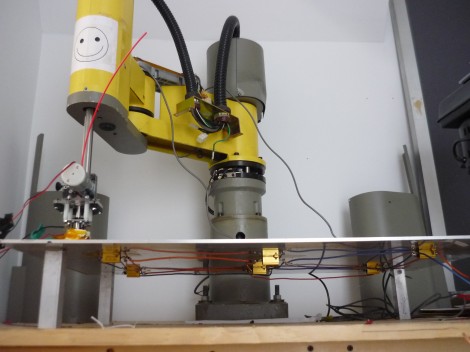
Wow, building a precision 3d printer is amazingly easy if you can get your hands on an industrial-quality robot arm. [Dane] wrote in to tell us about this huge extruder printer made from an ’80s-era SCARA robot arm. It is capable of printing objects as large as 25″x12″x6.5″.

This 190 pound beast was acquired during a lab clean out. It was mechanically intact, but missing all of the control hardware. Building controllers was a bit of a challenge since the it’s designed with servo motors and precision feedback sensors. This is different from modern 3d printers which use stepper motors and no feedback sensors. A working controller was built up one component at a time, with a heated bed added to the mix to help prevent warping with large builds. We love the Frankenstein look of the controller hardware, which was mounted hodge-podge as each new module was brought online.

You can see some printing action in the clip after the break. A Linux box takes a design and spits out control instructions to the hardware.

Continue reading “Salvaged Robot Arm Makes A Big 3d Printer”

Mini Waterproof LED Lanterns Charge Without Wires

inductive-charge-led-lights

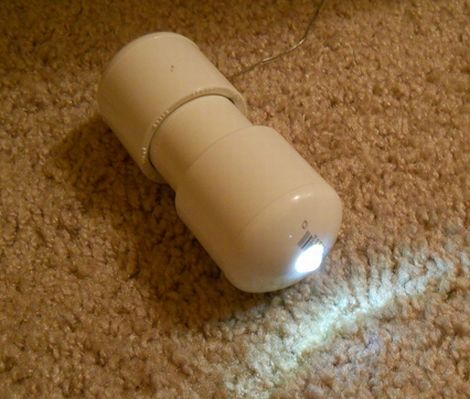
If you’re in search of a flashlight that can stand up to the elements, or simply looking for an easy way to spruce up your pool for those hot summer nights, check out these rechargeable PVC LED lights. Inspired by a post in Make: Magazine featuring Indestructible LED Lanterns, [John Duffy] decided to take the project one step further.

While he liked Make’s iteration of the waterproof lantern, he thought it would be best to permanently seal the lights for maximum durability. Not satisfied with a one-use light, he equipped the PVC lanterns with a single rechargeable AA battery, step-up circuitry to drive the LED, and an inductive charging coil.

His floating, waterproof lights sport a slightly bigger footprint than their predecessors to house the extra electronics, but we think that’s more than a fair trade off considering they can be charged wirelessly.

Place your Digikey/Mouser/Jameco orders now and check out [John’s] how-to video – you just might get some of these built in time for the weekend!

[via HackedGadgets]

Continue reading “Mini Waterproof LED Lanterns Charge Without Wires”

STM32 Demo Code Carries Extra (hidden?) Copyrights

Recently I started a repository that houses a template which may be used to compile STM32F0 projects with a GCC toolchain. There are two code packages from STM that I used when putting this together, the firmware for the Discovery board itself, and the Standard Peripheral Library for the chip family. I read the license agreements in the root of both packages and I think they’re quite fair. Basically the agreement is you can use them for any purposes as long as the code is only being used on STM hardware. Fair enough.

You can image I was quite upset so see a comment from a reader stating that I have a copyright violation with one of the files in the repo. It seems the linker script that is given as an example for Atollic’s TrueSTUDIO has it’s own extremely strict copyright:

** (c)Copyright Atollic AB.
** You may use this file as-is or modify it according to the needs of your
** project. Distribution of this file (unmodified or modified) is not
** permitted. Atollic AB permit registered Atollic TrueSTUDIO(R) users the
** rights to distribute the assembled, compiled & linked contents of this
** file as part of an application binary file, provided that it is built
** using the Atollic TrueSTUDIO(R) toolchain.

First off, I’m in violation just for posting the file in a repository. But read a bit deeper. Any code that is compiled with this using a GCC toolchain also breaks the copyright unless it’s Atollic’s toolchain.

My beef here is that STM is distributing this. Why? Why put something so restrictive into a software library with such an otherwise reasonable license? Surely there are many engineers at STM capable of writing a linker script that they could release under their own license which would work with TrueSTUDIO. And, it would have the added benefit of allowing other GCC-based toolchains a convenient (and legal) method of linking code.

So I’ve completely removed the file from the repository. If you were one of the ten people watching it on github, this had the unintended consequence of dumping your watch request. In the mean time I’m trying to learn how to write my own linker. This guide regarding Cortex-M3 linkers has been a great help. If you have the skills to contribute a working linker script, please issue a pull request or raise an issue over at github.

Multi-channel Analog Input Module Is A Good Jumping-off Point For Many Projects

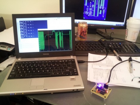
[Scott Harden] has already produced some projects which measure analog inputs. But he’s got plans for more and wanted a base system for graphing analog signals. You can see the small board next to his laptop which offers the ability to sample up to six signals and push them to a PC via USB.

The ATmega48 and a few supporting components are all you’ll find on that board. The USB connection is taken care of by an FTDI cable. He went that route because the cables are relatively cheap, easy to come by, and already have driver support on all the major operating systems. If you look at the screen you can see a window graphing one analog input in real-time. He wrote this in Python (which is once again a cross-platform tool) and it has no problem graphing all six inputs at once.

This is immediately useful as an upgrade to [Scott’s] ECG machine. His future plans include a Pulse Oximeter, EEG, and EEG.

Using Solar Cells To Track The Sun For Your Solar Cells (dawg)

This solar panel tracks the sun using solar cells. It’s a pretty interesting technique, and can be done on the cheap.

The rectangular panels are doing the actual energy harvesting. The circular modules seen below are solar cells from some landscaping lights. They’re being used as sensors to help judge if the device is aimed directly at the sun. We’ve already seen this type of thing done with a quartet of light dependent resistors. In this case, if the negative leads for both landscaping lights are connected, a voltage may be read from the positive lead of each panel. If you measure that voltage, and use a rotating stand to adjust the position until the readings balance, you can be assured that your array is getting the optimal amount of sunlight.

[Gtoal] had been trying to drive motors directly from the output lines of these panels without success. We’re sure there’s a simple analog comparator circuit which would facilitate this. Grabbing a small microcontroller is another option (and some chips have an analog comparator built in).

Driving A PSP Screen With An FPGA

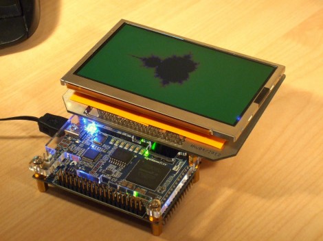
Here’s [FlorianH’s] setup for driving a PlayStation Portable screen with an FPGA. He’s using the DE0-Nano board to do this, and the first order of business was to establish a way to connect the two. He did a great job of etching his own breakout board, which has some traces that are less than 10 mils thick. Soldering the connectors for the screen was a bit of a challenge, and he shared several pictures of the process for your enjoyment.

With everything hooked up he fired it up with just a couple of lines of code to draw a test pattern. From there it was on to building a more intensive driver. [FlorianH] mentioned to us that he’s just starting to learn about FPGAs after having worked extensively with 8-bit microcontrollers. He’s been documenting his work on his site, and finds himself frequently referencing his own material so remember how he did things. Our vicarious enjoyment is an unintended (but welcomed) consequence of that habit.