The Original Seven (Eight?) Segment Display

The seven-segment LED display is ubiquitous. But how old do you think the fundamental idea behind it is? You nixie tube fans will be thinking of the vacuum-tube era, but a reader sent us this patent filed in 1908 where [Frank W. Wood] builds a numeric display with plain-vanilla light bulbs, slots cut in wood, and lots of wires.

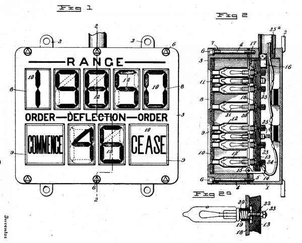
The OCR on the patent is poorly done — you’re going to want to download the PDF and read it locally. But as it states in the patent, “Referring again to Fig. 1, the novel arrangement of the lamp compartments will be readily understood.”

Technically it’s not a seven-segment display at all. [F.W. Wood] designed these really nice-looking “4”s with the diagonal heads, and so he needed eight segments per digit. But the basic idea shines through, if you pardon the pun.

The other figures demonstrate the machine that’s used to send the signals to light up the lights. It’s a rotating drum with the right contacts on the bottom side to make connections and turn on the right lights at the other end. Low tech, but it’s what was available at the time.

We’re stoked that we’re not responsible for wiring this thing up, and we’re a bit awed by how old the spirit behind one of our most ubiquitous technologies is.

Thanks to [mario59] for the nostalgic tip!

Everyone’s Favorite Energy Meter Hack, Now Wireless

[Kalle] is at it again with more hacks on electricity use meters. This time, the meter has been hacked to stream their data over the aether wirelessly. Now, data can be grabbed from multiple devices simultaneously, making the possibilities for home energy monitoring limitless

The first project [Kalle] did involved finding a meter from China with capabilities similar to (and cheaper than) the Kill-a-Watt meters. Unlike the Kill-a-Watt which spits out analog values, the Chinese meter sent digital information out on a ribbon cable with the bus lines labeled. Since the meter was so hackable, [Kalle] took it even further in this hack.

With those pesky wires out of the way, the device now uses an Arduino Pro Mini to sniff the energy meter’s data stream. Then it transmits the data wirelessly with a nRF34L01+ transceiver. As a perk, all of these chips fit inside the case of the energy meter, making this a very tidy hack indeed. The project code an incredible amount of detail is available on the project site, so be sure to check this one out for all of your energy monitoring needs!

Putting Lightning In Acrylic

Some folks at the i3Detroit hackerspace had an opportunity come up that would allow them to capture lightning in acrylic. They created a few Lichtenberg figures thanks to the help of a plastic tubing manufacturer, some lead sheet and a bunch of 1/2″ thick acrylic.

Lichtenberg figures are the 3D electrical trees found in paperweights the world over. They’re created through electrical discharge through an insulator, with lightning being the most impressive Lichtenberg figure anyone has ever seen. These figures can be formed in smaller objet d’art, the only necessity being a huge quantity of electrons pumped into the insulator.

This was found at Mercury Plastics’ Neo-Beam facility, a 5MeV electron accelerator that’s usually used to deliver energy for molecular cross linking in PEX tubing to enhance chemical resistance. For one day, some of the folks at i3Detroit were able to take over the line, shuffling a thousand or so acrylic parts through the machine to create Lichtenberg figures.

When the acrylic goes through the electron accelerator, they’re loaded up with a charge trapped inside. A quick mechanical shock discharges the acrylic, creating beautiful tree-like figures embedded in the plastic. There are a lot of pictures of the finished figures in a gallery, but if you want to see something really cool, a lead-shielded GoPro was also run through the electron accelerator. You can check out that video below.

Continue reading “Putting Lightning In Acrylic”

Binary Clock

Binary Clock Would Make Doc Brown Proud

[Brett] was looking for a way to improve on an old binary clock project from 1996. His original clock used green LEDs to denote between a one or a zero. If the LED was lit up, that indicated a one. The problem was that the LEDs were too dim to be able to read them accurately from afar. He’s been wanting to improve on his project using seven segment displays, but until recently it has been cost prohibitive.

[Brett] wanted his new project to use 24 seven segment displays. Three rows of eight displays. To build something like this from basic components would require the ability to switch many different LEDs for each of the seven segment displays. [Brett] instead decided to make things easier by using seven segment display modules available from Tindie. These modules each contain eight displays and are controllable via a single serial line.

The clock’s brain is an ATmega328 running Arduino. The controller keeps accurate time using a DCF77 receiver module and a DCF77 Arduino library. The clock comes with three display modes. [Brett] didn’t want and physical buttons on his beautiful new clock, so he opted to use remote control instead. The Arduino is connected to a 433MHz receiver, which came paired with a small remote. Now [Brett] can change display modes using a remote control.

A secondary monochrome LCD display is used to display debugging information. It displays the time and date in a more easily readable format, as well as time sync information, signal quality, and other useful information. The whole thing is housed in a sleek black case, giving it a professional look.

Using The Wink Hub With OpenHAB

Spend enough time looking at home automation setups, and you’ll quickly find there are two competing philosophies. The first wants to put an Arduino on every light socket, with everything connected by cheap eBay radio modules. The second home automation philosophy requires astonishingly expensive hardware to talk to other expensive modules. The Arduino solution is a system that can be infinitely customizable, and the commercial solution talks to ‘the cloud’ for some strange reason. There is no middle ground. At least there wasn’t until [Eric] started poking around and looked at a few hardware solutions.

[Eric] was looking to control some GE Link bulbs through his phone, computer, or through the Internet. They’re supposed to be the best bulb on the market in terms of price and performance, but they can only be controlled with a Zigbee. This lead [Eric] to an interesting hack that gave all owners of the Wink Hub local control of their devices. From [Eric]’s research, this was the only way his lighting wasn’t dependent on ‘the cloud’.

Local control of the Wink was only possible after [Eric] read a post on rooting the Wink (and this post from a few days ago). Because the device could be rooted, and the fact that [Eric] already has a few things in his house integrated with OpenHAB, the choice on how to proceed with controlling a few Zigbee enabled lights was easy.

Once [Eric] got the light bulbs talking to the Wink, integrating them with the rest of the devices in his home was easy. The new bulbs are activated with his Arduino motion sensors, door sensors, and can be controlled via smartphone or by voice control. The Wink can also be completely disconnected from the Internet. A good idea, because the ability to turn a light on and off should not be dictated by the quality of your Internet connection.

Continue reading “Using The Wink Hub With OpenHAB”

DIY guitar mute pedal

Guitar Mute Pedal Made From Upcycled Parts

Rockin’ out on your fave guitar is pretty fun for sure but whether your on stage or jamming in your basement, it can be convenient to quickly mute those killer licks. [wozlaser] wanted a mute pedal for his guitar and instead of shelling out the tens of dollars for a commercial version, he decided to build one himself.

This pedal is heavy-duty and made out of metal. If the frame looks familiar, that is because in a prior life this was a control pedal for a sewing machine. [wozlaser] found it cheap at a thrift store. After the internals were taken out, he added a few key parts. First were the 1/4″ input and output jacks that were scavenged from an old stereo system. There is a momentary switch from a VCR and a standard guitar stomp pedal switch mounted all the way in the front of the frame. The wiring is as follows:

DIY guitar mute pedal

The wiring schematic is pretty darn simple, it just grounds and ungrounds the signal wire. As stated earlier, there are 2 switches, a momentary and a push-on/push-off switch. A normal mute pedal would only have one switch but [wozlaser] wanted something special. If you push the pedal all the way forward it will mute or unmute the signal until it is pushed again. When the pedal is in the spring-supported ‘up’ position a lever pushes on the momentary switch, a slight push on the pedal lifts the lever off of the momentary switch to mute or unmute the signal. The function of the momentary switch (mute or unmute) changes with the state of the other switch. This works exactly the same as a 3-way light switch circuit allows two switches to control one light in your house. With this setup [wozlaser] is able to not only mute and unmute his guitar but strum a chord with it off and pulse the chord on to the beat of the music or tap the pedal with some guitar feedback to make the sound cut in and out. All that only cost [wozlaser] a little time and spare parts… and there are no batteries to replace!

LED necklace

IBling Is An LED Display Necklace

Are you tired of being ignored? Do you want a fashion accessory that says, “Pay attention to me!” If so, you should check out [Al’s] recent instructable. He’s built himself a necklace that includes a display made up of 512 individual LEDs.

This project was built from mostly off-the-shelf components, making it an easy beginner project. The LED display is actually a product that you can purchase for just $25. It includes 512 LEDs aligned in a 16 x 32 grid. The module is easily controlled with a Pixel maker’s kit. This board comes with built-in functionality to control one of these LED modules and can accept input from a variety of sources including Android or PC. The unit is powered from a 2000 mAH LiPo battery.

[Al] had to re-flash the firmware of the Pixel to set it to a low power mode. This mode allows him to get about seven hours of battery life with the 2000 mAH battery. Once the hardware was tested and confirmed to work correctly, [Al] had to pretty things up a bit. Some metallic gold spray paint and rhinestones transformed the project’s cyberpunk look into something you might see in a hip hop video, or at least maybe a Weird Al hip hop video.

The Pixel comes with several Android apps to control the display via Bluetooth. [Al] can choose one of several modes. The first mode allows for pushing animated gif’s to the display. Another will allow the user to specify text to scroll on the display. The user can even specify the text using voice recognition. The final mode allows the user to specify a twitter search string. The phone will push any new tweets matching the terms to the display as scrolling text.