There’s nothing like a good clock project, and tacking the steampunk modifier on it only makes it better. [José] built a steampunk clock that does it much better than just gluing some gears on an enclosure and calling it a day. This build includes glowing jewels displaying the time in different colors while displaying the a steampunker’s prowess with a pipe cutter.
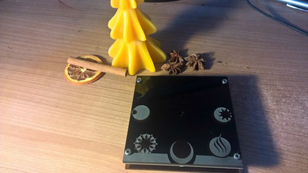
The body of the clock is a piece of finely lacquered wood, hiding a perfboard construction with a DS3231 real time clock, a DHT22 temperature and humidity sensor, and a light sensor for dimming the WS2812 LEDs according to the ambient light level.
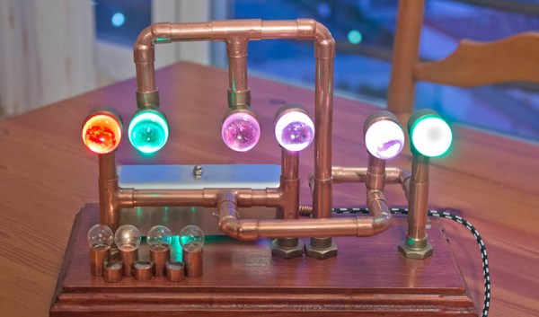
The rest of the clock is a bunch of 12mm copper pipe, elbows, and t couplers. The end of these pipes are capped off with marbles, with the RGB LEDs behind each of the ‘digits’ of the clock. This is a chromatic clock, with the digits 0 through 9 assigned a different color, based on the resistor color code scheme with exceptions for black and brown. Once you’ve figured out how to tell time with this clock, you should have no problem finding that single 56k resistor in your junk box.
You can check out the video of the clock below.


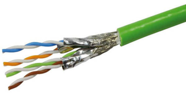
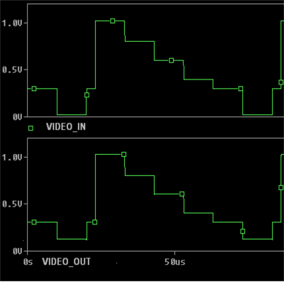 A differential amplifier usually requires a dual-polarity power supply, which may not be available when adding this upgrade to an existing system. To over come this limitation, [Maurizio] uses a bias voltage equal to half of the power supply value. This bias voltage is added to the non-inverting amplifier signal, and subtracted from the inverting amplifier signal. The resultant differential signal is then fed into the twisted pair cable through impedance matching resistors. At the receiving end, a single amplifier receives the differential signals and outputs a signal that corresponds to the original video signal.


