RTLSDR

Decoding Satellite-based Text Messages With RTL-SDR And Hacked GPS Antenna

[Carl] just found a yet another use for the RTL-SDR. He’s been decoding Inmarsat STD-C EGC messages with it. Inmarsat is a British satellite telecommunications company. They provide communications all over the world to places that do not have a reliable terrestrial communications network. STD-C is a text message communications channel used mostly by maritime operators. This channel contains Enhanced Group Call (EGC) messages which include information such as search and rescue, coast guard, weather, and more.

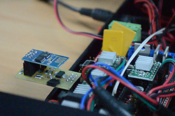
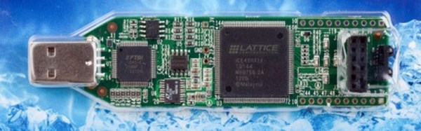
Not much equipment is required for this, just the RTL-SDR dongle, an antenna, a computer, and the cables to hook them all up together. Once all of the gear was collected, [Carl] used an Android app called Satellite AR to locate his nearest Inmarsat satellite. Since these satellites are geostationary, he won’t have to move his antenna once it’s pointed in the right direction.

Hacked GPS antenna
Hacked GPS antenna

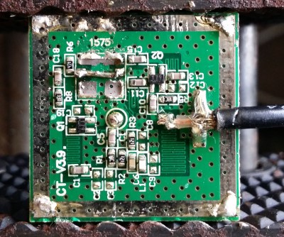
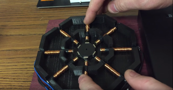
As far as antennas go, [Carl] recommends a dish or helix antenna. If you don’t want to fork over the money for something that fancy, he also explains how you can modify a $10 GPS antenna to work for this purpose. He admits that it’s not the best antenna for this, but it will get the job done. A typical GPS antenna will be tuned for 1575 MHz and will contain a band pass filter that prevents the antenna from picking up signals 1-2MHz away from that frequency.

To remove the filter, the plastic case must first be removed. Then a metal reflector needs to be removed from the bottom of the antenna using a soldering iron. The actual antenna circuit is hiding under the reflector. The filter is typically the largest component on the board. After desoldering, the IN and OUT pads are bridged together. The whole thing can then be put back together for use with this project.

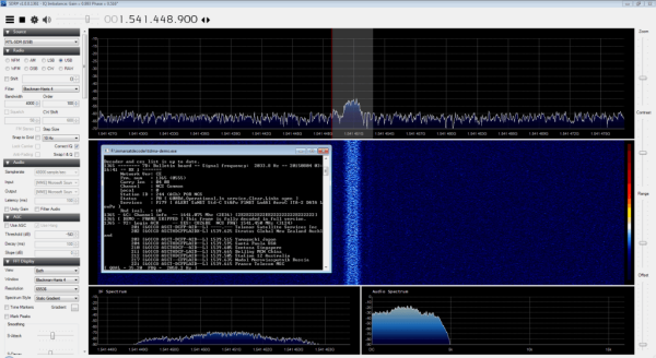
Once everything was hooked up and the antenna was pointed in the right place, the audio output from the dongle was piped into the SDR# tuner software. After tuning to the correct frequency and setting all of the audio parameters, the audio was then decoded with another program called tdma-demo.exe. If everything is tuned just right, the software will be able to decode the audio signal and it will start to display messages. [Carl] posted some interesting examples including a couple of pirate warnings.

If you can’t get enough RTL-SDR hacks, be sure to check out some of the others we’ve featured in the past. And don’t forget to send in links to your own hacking!

Remote Start Jeep

Okay, Google. Start The Jeep!

When [wizardpc] bought his Jeep, it came with an Avital 3100L car alarm system; but after it started going on the fritz, he needed to replace it. So he opted for a new alarm system with the same harness type — and then he decided to hack it.

When installing the new alarm system, an Avital 5103L combo unit, he realized there was an extra wire that when grounded, starts the vehicle — Avital had included the hardware upgrade before the software came out on this specific model. Score.

From there it was a pretty easy hack. All he needed was a Raspberry Pi 2, a relay board, and a few dirt simple lines of code. On the mobile end of things is a collection of hacks; he’s using Tasker with his Android phone to add a special command to Google Now. He tells Google to ‘Start the Jeep’ and after a few seconds, she turns right on.

Wouldn’t it be nice if Google would expose some hooks so that we can all add our own functionality to Google Now without doing the app-juggling  [wizardpc] used for this? If you have your own set of Google Now hacks we’d love to hear about it. Send us a tip!

Continue reading “Okay, Google. Start The Jeep!”

Hackaday Prize Entry: Lighting The Way For Walkers

Chances are, you probably know someone who uses a walker to assist in their mobility. Ever wonder about how they could be made better? When [Alan McFarland] noticed his friend using his iPhone as a light to walk down a hallway — with only one hand on his walker — he realized something could easily be done to make the walker more functional. His own light bar.

Sure you could get a flashlight, zip tie it to the walker, or maybe a bike light with a dedicated mount — but [Alan] wanted it to be a bit more elegant; and functional. With this in mind, he attached an LED light strip to the lower frame of the walker to help illuminate the path ahead. A button is wired up to the handle for easy access, and he’s even using a PIC12F1501 microcontroller to give it some logic — it’ll turn off by itself, fading out, giving the person a chance to sit down before the lights go out.

The thing we like about this project is he programmed it using the PICBASIC PRO compiler — the same compiler that [Alan] himself used nearly 20 years ago programming the Borg suits and spacesuit lighting on Star Trek: First Contact — how’s that for a random trivia fact!

The 2015 Hackaday Prize is sponsored by:

Hello RAMPS, Meet ESP8266

The proliferation of  DIY 3D printers has been helped in large measure by the awesome open-source RepRap project. A major part of this project is the RAMPS board – a single control board / shield to which all of the other parts of the printer can be easily hooked up. A USB connection to a computer is the usual link of choice, unless the RAMPS board has the SD-Card option to allow the 3D printer to operate untethered. [Chetan Patil] from CreatorBot built a breakout board to help attach either the ESP8266 WiFi or the HC-05 Bluetooth module to the Aux-1 header on the RAMPS board. This lets him stream G-code to the printer and allow remote control and monitoring.

While the cheap ESP8266 modules are the current flavor of the season with Hackers, getting them to work can be quite a hair tearing exercise. So [Chetan] did some hacking to figure out the tool chain for developing on the ESP module and found that LUA API from NodeMcu would be a good start. The breakout board is nothing more than a few headers for the ESP8266, the HC-05 and the Aux-1 connections, with a few resistors, a switch to set boot loader mode and a 3.3V regulator. If you’re new to the ESP8266, use this quick, handy, guide by [Peter Jennings] to get started with the NodeMCU and Lualoader. [Chetan]’s code for flashing on the ESP8266, along with the Eagle board design files are available via his Github repo. Just flash the code to the ESP8266 and you’re ready to go.

One gotcha to be aware of is to plug in the ESP module after the printer has booted up. Otherwise the initial communication from the ESP module causes the printer to lock up. We are sure this is something that can be taken care of with an improved breakout board design. Maybe use a digital signal from the Arduino Mega on the RAMPS board to keep the ESP module disabled for a while during start up, perhaps? The video after the break gives a short overview of the hack.

Continue reading “Hello RAMPS, Meet ESP8266”

Hack Your Own Analog Camera

We remember making pinhole cameras as kids out of cigar boxes. The Focal Camera website wants to enable you to make sophisticated cameras from a selection of building blocks. We’re talking cameras with film, not digital cameras (although we wondered if you could mount an image sensor… but that’s another hack).

The modules do require access to a laser cutter, and you’ll need to scrounge or otherwise acquire things like mirrors and lenses. The site has advice on how to hack things like first surface mirrors out of cheap items like acrylic mirrors.

The intent is to be able to build up your own cameras from the modules. They do have a pinhole camera, in case you are nostalgic, but you could also build SLRs, large format cameras, or even stereo cameras. Not all the modules are ready yet, but there are several example cameras and pictures taken with them on the site. Like most building blocks, the real treat will be when users begin to combine them in unexpected ways.

Continue reading “Hack Your Own Analog Camera”

Giant Stepper Motor Gets You Up To Speed On Theory

Few hackers have trouble understanding basic electric motors. We’ve all taken apart something that has a permanent magnet DC motor in it and hooked up its two leads to a battery to make it spin. Reverse the polarity, reverse the spin; remove the power, stop the spin. Stepper motors (and their close cousins, brushless DC motors) are a little tougher to grok, though, especially for the beginner. But with a giant 3D printed stepper motor, [Proto G] has made getting your head around electronically commutated motors a little easier.

While we’ve seen 3D printed stepper motors before, the size and simple layout of this one really lends to understanding the theory. With a 3D-printed frame, coils wound on nails, and rare-earth magnets glued to a rotor, this is an approachable build that lays the internals of a stepper motor out for all to see and understand. You can easily watch how the rotor lines up as the various coils are energized in a circular pattern, although it might be more revealing to include bi-color LEDs to indicate which coils are energized and what the polarity is. Those would be especially helpful demonstrating the concept of half-stepping. We’d also like to see more detail on the controller electronics, although admittedly all the video-worthy action is in the motor itself.

Continue reading “Giant Stepper Motor Gets You Up To Speed On Theory”

Learning Verilog For FPGAs: Flip Flops

Last time I talked about how to create an adder in Verilog with an eye to putting it into a Lattice iCEstick board. The adder is a combinatorial circuit and didn’t use a clock. This time, we’ll finish the demo design and add two clocked elements: a latch that remembers if the adder has ever generated a carry and also some counters to divide the 12 MHz clock down to a half-second pulse to blink some of the onboard LEDs.

Why Clocks?

Clocks are an important part of practical digital design. Suppose you have a two input AND gate. Then imagine both inputs go from zero to one, which should take the output from zero to one, also. On paper, that seems reasonable, but in real life, the two signals might not arrive at the same time. So there’s some small period of time where the output is “wrong.” For a single gate, this probably isn’t a big deal since the delay is probably minuscule. But the errors will add up and in a more complex circuit it would be easy to get glitches while the inputs to combinatorial gates change with different delays.

Continue reading “Learning Verilog For FPGAs: Flip Flops”