Retrotechtacular: One Does Not Simply String Up A Half-Million VDC Transmission Line

It takes strong and determined population to build a lasting civilization. If the civilization includes electricity and the inhabitants live in a hilly place with an often-unforgiving climate, the required strength and determination increases proportionally. Such is the case of the gentlemen who strung up the first half-million VDC transmission line across New Zealand, connecting the country’s two main islands.

Construction for the line known as the HVDC Inter-Island link began in 1961. It starts at the Benmore hydroelectric plant on the south island and runs north to Cook Strait via overhead cables. Then it travels 40km underwater to the north island and ends near Wellington. This is the kind of infrastructure project that required smaller, preliminary infrastructure projects. Hundreds of miles of New Zealand countryside had to be surveyed before breaking ground for the first tower support hole. In order to transport the materials and maintain the towers, some 270 miles of road were laid and ten bridges were built. Fifteen camps were set up to house the workers.

The country’s hilly terrain and high winds made the project even more challenging. But as you’ll see, these men were practically unfazed. They sent bundles of steel across steep canyons on zip lines and hand-walked wire haulage rope across gullies because they couldn’t otherwise do their job. Six of these men could erect a tower within a few hours, which the filmmakers prove with a cool time-lapse sequence.

Splicing the mile-long conductors is done with 100-ton compressors. Each connection is covered with steel sleeve that must be centered across the joint for optimum transmission. How did they check this? By taking a bunch of x-rays with a portable cesium-137 source.

Continue reading “Retrotechtacular: One Does Not Simply String Up A Half-Million VDC Transmission Line”

Learning Verilog For FPGAs: The Tools And Building An Adder

Over the last year we’ve had several posts about the Lattice Semiconductor iCEstick which is shown below. The board looks like an overgrown USB stick with no case, but it is really an FPGA development board. The specs are modest and there is a limited amount of I/O, but the price (about $22, depending on where you shop) is right. I’ve wanted to do a Verilog walk through video series for awhile, and decided this would be the right target platform. You can experiment with a real FPGA without breaking the bank.

In reality, you can learn a lot about FPGAs without ever using real hardware. As you’ll see, a lot of FPGA development occurs with simulated FPGAs that run on your PC. But if you are like me, blinking a virtual LED just isn’t as exciting as making a real one glow. However, for the first two examples I cover you don’t need any hardware beyond your computer. If you want to get ready, you can order an iCEstick and maybe it’ll arrive before Part III of this series if published.

Continue reading “Learning Verilog For FPGAs: The Tools And Building An Adder”

Google’s OnHub Goes Toe To Toe With Amazon Echo

Yesterday Google announced preorders for a new device called OnHub. Their marketing, and most of the coverage I’ve seen so far, touts OnHub as a better WiFi router than you are used to including improved signal, ease of setup, and a better system to get your friends onto your AP (using the ultrasonic communication technique we’ve also seen on the Amazon Dash buttons). Why would Google care about this? I don’t think they do, at least not enough to develop and manufacture a $199.99 cylindrical monolith. Nope, this is all about the Internet of Things, as much as it pains me to use the term.

google-onhub-iot-router-thumbOnHub boasts an array of “smart antennas” connected to its various radios. It has the 2.4 and 5 Gigahertz WiFi bands in all the flavors you would expect. The specs also show an AUX Wireless for 802.11 whose purpose is not entirely clear to me but may be the network congestion sensing built into the system (leave a comment if you think otherwise). Rounding out the communications array is support for ZigBee and Bluetooth 4.0.
I have long looked at Google’s acquisition of Nest and assumed that at some point Nest would become the Router for your Internet of Things, collecting data from your exercise equipment and bathroom scale which would then be sold to your health insurance provider so they may adjust your rates. I know, that’s a juicy piece of Orwellian hyperbole but it gets the point across rather quickly. The OnHub is a much more eloquent attempt at the same thing. Some people were turned off by the Nest because it “watches” you to learn your heating preferences. The same issue has arisen with the Amazon Echo which is “always listening”.

Google has foregone those built-in futuristic features and chosen a device to which almost  everyone has already grown accustom: the WiFi router. They promise better WiFi and I’m sure it will deliver. What’s the average age of a home WiFi AP at this point anyway? Any new hardware would be an improvement. Oh, and when you start buying those smart bulbs, fridges, bathroom scales, egg trays, and whatever else it’ll work for them as well.

As far as hacking and home automation, it’s hard to beat the voice-activated commands we’ve seen with Echo lately, like forcing it to control Nest or operate your Roku. Who wants to bet that we’ll see a Google-Now based IoT standalone device quickly following the shipment of OnHub?

Continue reading “Google’s OnHub Goes Toe To Toe With Amazon Echo”

The EM Drive Might Not Work, But We Get Helicarriers If It Does

There is a device under test out there that promises to take humans to another star in a single lifetime. It means vacations on the moon, retiring at Saturn, and hovercars. If it turns out to be real, it’s the greatest invention of the 21st century. If not, it will be relegated to the history of terrible science right underneath the cold fusion fiasco. It is the EM drive, the electromagnetic drive, a reactionless thruster that operates only on RF energy. It supposedly violates the laws of conservation of momentum, but multiple independent lab tests have shown that it produces thrust. What’s the real story? That’s a little more complicated.

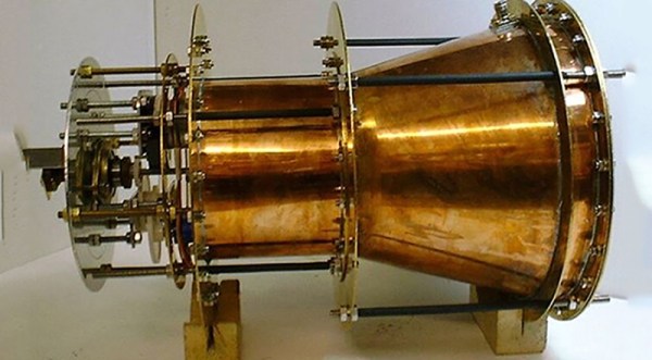
The EM Drive is a device that turns RF energy — radio waves — directly into thrust. This has obvious applications for spacecraft, enabling vacations on Mars, manned explorations of Saturn, and serious consideration of human colonization of other solar systems. The EM drive, if proven successful, would be one of the greatest inventions of all time. Despite the amazing amount of innovation the EM drive would enable, it’s actually a fairly simple device, and something that can be built out of a few copper sheets.

Continue reading “The EM Drive Might Not Work, But We Get Helicarriers If It Does”

Color By Number 3D Printing Style

Remember paint-by-number kits? Your canvas has outlines with numbered regions that you paint with correspondingly numbered paints. When you are done, you’ve recreated the Mona Lisa. [KurtH3] uses a similar technique to coax multicolor prints from his 3D printer.

The technique isn’t general purpose, but it still is an interesting way to add some color to your usually monochrome prints. The idea is simple: You find a paint-by-number layout (apparently, you can find them with a Google search). Use your favorite method to get the outline into a CAD program. [KurtH3] doesn’t really get into the details about this, but some CAD programs will directly import images. Others will require you to trace in Inkscape (or a similar program) and convert to a vector format like DXF that the 3D CAD program can import.

Here’s the trick: instead of extruding the 2D image as one piece, you extrude the numeric regions to slightly different heights. Say you wanted to print a red, white, and blue flag to a thickness of about 5mm and you use 0.2mm layers. You could extrude the white part to 5mm, for example. Then the red parts could be extruded to 5.2mm (one layer higher) and the blue parts to 5.4mm. You could extend the idea to do multiple layers, although that will increase the surface roughness.

[KurtH3] pauses the print at the end of the layers to change filament, but we would probably edit the sliced G-Code to put pauses in the right places (for example, Repetier Host lets you put @pause in your file). You could also use software to split the G-Code as we’ve previously covered.  The resulting print, using our example, would be white from the bottom up but would have thin red and blue layers over the top in the right places. The few hundred microns difference from the white surface to the other colors means you won’t get a perfectly smooth surface, but a few hundred microns shouldn’t be too noticeable.

Continue reading “Color By Number 3D Printing Style”

Microcontroller Adjustment Of A DC To DC Converter

[Hugatry] wanted to replace the adjustment pot on an LM2596 buck converter with a microprocessor-controlled voltage. The regulator IC uses a divider to generate a 1.25V reference from the output. The pot is part of a divider circuit that sets the output voltage. For example, if the divider is 10:1, the controller will keep the output at 1.25V and, therefore, the output voltage will be 12.5V.

[Hugatry’s] strategy was to use a filtered PWM signal from a microcontroller to offset the 1.25V signal. By adding a small voltage to the control point, the output voltage would not need to rise as high as before to maintain the 1.25V reference. For example, adding 0.25V to the reference input would only require 1V, which corresponds to a 10V output.

The video has a nice view of a scope showing the relationship between the PWM duty cycle and the output voltage. Although he didn’t mention it, it struck us that since PWM is proportional to the supply voltage, the voltage on the microcontroller and PWM output stage probably needs to be fixed. That implies you couldn’t use the buck converter to directly power the microcontroller itself. Then again, what kind of microcontroller needs to adjust its own power supply?

Continue reading “Microcontroller Adjustment Of A DC To DC Converter”

Hackaday Prize Entry: The 70s Called. They Want This Calculator

For those of us who grew up during TI’s calculator revolution, the concept of reverse polish notation (RPN) might be foreign. For other more worldly calculator users, however, the HP calculator was ubiquitous. Hewlett-Packard peaked (at least as far as calculators are concerned) decades ago and the market has remained dominated by TI since. Lucky for those few holdouts there is now a new microcode emulator of these classic calculators.

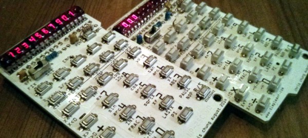
Called the NP25 (for Nonpariel Physical), the calculator fully emulates the HP-21, HP-25C and HP-33C. It’s a standalone microcode emulator, which means that these calculators work exactly as well as the original HP calculators of the 70s did. The new calculators, however, are powered by a low power MSP430G2553 processor and presumably uses many, many fewer batteries than the original did. It has an LED display to cut power costs as well, and was built with the goal of being buildable by the average electronics hobbyist.

Even if you didn’t grow up in the 70s with one of these in your desk drawer, it’d still be a great project and would help even the most avid TI user appreciate the fact that you don’t have to use RPN to input data into calculators anymore. Not that there’s anything wrong with that. This isn’t the only calculator we’ve featured here, either, so be sure to check out another free and open calculator for other calculator-based ideas.

Continue reading “Hackaday Prize Entry: The 70s Called. They Want This Calculator”