Spoofing Cell Networks With A USB To VGA Adapter

RTL-SDR brought cheap and ubiquitous Software Defined Radio (SDR) to the masses, opening up whole swaths of the RF spectrum which were simply unavailable to the average hacker previously. Because the RTL-SDR supported devices were designed as TV tuners, they had no capability to transmit. For the price they are still an absolutely fantastic deal, and deserve to be in any modern hacker’s toolkit, but sometimes you want to reach out and touch someone.

GSM network broadcast from a VGA adapter

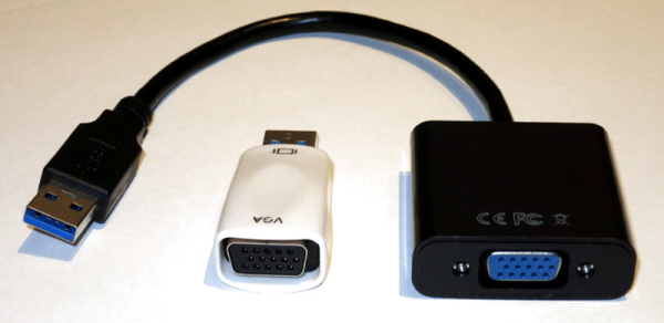
Now you can. At OsmoDevCon [Steve Markgraf] released osmo-fl2k, a tool which allows transmit-only SDR through cheap USB 3.0 to VGA adapters based on the Fresco Logic FL2000 chip. Available through the usual overseas suppliers for as little has $5 USD, these devices can be used unmodified to transmit low-power FM, DAB, DVB-T, GSM, UMTS and GPS signals.

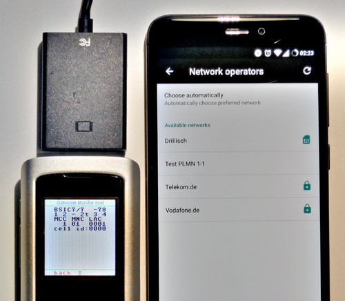
In a demonstration on the project page, one of these USB VGA adapters is used to broadcast a GSM cellular network which is picked up by the adjacent cell phones. Another example shows how it can be used to broadcast FM radio. A GitHub repository has been set up which includes more examples. The signals transmitted from the FL2000 chip are obviously quite weak, but the next step will logically be the hardware modifications necessary to boost transmission to more useful levels.

To say this is a big deal is something of an understatement. For a few bucks, you’ll be able to get a device to spoof cellular networks and GPS signals. This was possible before, of course, but took SDR hardware that was generally outside the budget of the casual experimenter. If you bought a HackRF or an Ettus Research rig, you were probably responsible enough not to get into trouble with it, but that’s not necessarily the case anymore. As exciting as this technology is, we would be wise to approach it with caution. In an increasingly automated world, GPS spoofing can have some pretty bad results.

The Simplest Possible DIY Ultrasonic Levitator

We thought that making things levitate in mid-air by the power of sound was a little bit more like magic, or at least required fancy equipment. It turns out that you can do it yourself easily enough with parts that any decent hacker’s closet should have in abundance: a motor-driver IC, two ultrasonic distance pingers, and a microcontroller. This article shows you how (translated here, scroll down).

But aside from a few clever tricks, there’s not that much to show. The two HC-SR04 ultrasonic distance sensors are standard fare, and are just being used as a cheap source of 40 kHz transducers. The circuit uses a microcontroller, but any source of 40 kHz square waves should suffice. Those of you who could do that with a 555 (or a Raspberry Pi), this one’s for you! A stepper motor driver bumps up the voltage applied to the transducers, but you could use plain-vanilla transistors as well.

It’s all the little details that count, however. You need to position the two ultrasonic drivers fairly precisely to create a standing wave, and while you can start at 8.25 mm and trial-and-error it, the article demonstrates using an oscilloscope to align the capsules by driving one and reading the signal out of the other and tweaking them until they’re in phase. Clever!

The author also takes the ultrasonic-transparent grille from one of the unused receivers and uses it as a spoon to help position the styrofoam bits in the sound waves. We always wondered how you’d do that!

It turns out that it’s easy to make a DIY ultrasonic levitation desk toy, and none of the parts are expensive or critical. The missing ingredient is just the gumption to try it, and now we have that, too.

As cool as they are, the HC-SR04 modules aren’t perfect for all distance sensing applications. Here’s everything you need to know about them, including hacks to make them work up-close. And since HC-SR04 sensors come cheapest in ten-packs, you’ll be wondering what you’re going to do with the other eight. That problem has apparently also been solved.

Remote Control Of Clocks Is Easy As Pi

[Fatjedi007] recently acquired three programmable boxing gym-type clocks to help his developmentally disabled clients manage their time. The plan was to have timers of varying lengths fire at preset times throughout the day, with the large displays providing a view from anywhere. Unfortunately, the clocks were not nearly as programmable as he needed them to be.

Since he’d spent enough money already, [Fatjedi007] turned to the power of Raspberry Pi to devise an affordable solution. Each clock gets a Pi Zero W and a simple IR transmit/receive circuit that operates using LIRC. The clocks came with remote controls, so it was just a matter of re-programming them. From LIRC, he wrote some scripts with SEND_ONCE and schedules the timers with a cron job. No need to get out the ladder—he can program all of them from his chair over VNC.

He does have one problem, though, and that’s getting the Zeros to set themselves over NTP with static IPs. Do you have any suggestions? Put ’em in the comments and help a Jedi out.

LIRC is pretty handy for anything you want to control remotely, like a stereo system.

An FM Transceiver From An Unexpected Chip

The Si47xx series of integrated circuits from Silicon Labs is a fascinating series of consumer broadcast radio products, chips that apply SDR technologies to deliver a range of functions that were once significantly more complex, with minimal external components and RF design trickery.  [Kodera2t] was attracted to one of them, the Si4720, which boasts the unusual function of containing both a receiver and a transmitter for the FM broadcast band and is aimed at mobile phones and similar devices that send audio to an FM car radio. The result is a PCB with a complete transceiver controlled by an ATmega328 and sporting an OLED display, and an interesting introduction to these devices.

The Si4720 internal block diagram, from its data sheet.

A look at the block diagram from the Si4720 reveals why it and its siblings are such intriguing devices. On-chip is an SDR complete in all respects including an antenna, which might set the radio enthusiasts among the Hackaday readership salivating were it not that the onboard DSP is not reprogrammable for any other purpose than the mode for which the chip is designed. The local oscillator also holds a disappointment, being limited only to the worldwide FM broadcast bands and not some of the more useful or interesting frequencies. There are however a host of other similar Silicon Labs receiver chips covering every conceivable broadcast band, so the experimenter at least has a good choice of receivers to work with.

If you need a small FM transmitter and have a cavalier attitude to spectral purity then it’s easy enough to use a Raspberry Pi or just build an FM bug. But this project opens up another option and gives a chance to experiment with a fascinating chip.

Hackaday Links Column Banner

Hackaday Links: April 22, 2018

Eagle 9 is out. Autodesk is really ramping up the updates to Eagle, so much so it’s becoming annoying. What are the cool bits this time? Busses have been improved, which is great because I’ve rarely seen anyone use busses in Eagle. There’s a new pin breakout thingy that automagically puts green lines on your pins. The smash command has been overhauled and now moving part names and values is somewhat automatic. While these sound like small updates, Autodesk is doing a lot of work here that should have been done a decade ago. It’s great.

Crypto! Bitcoin is climbing up to $9,000 again, so everyone is all-in on their crypto holdings. Here’s an Arduino bitcoin miner. Stats of note: 150 hashes/second for the assembly version, and at this rate you would need 10 billion AVRs to mine a dollar a day. This array of Arduinos would need 2 Gigawatts, and you would be running a loss of about $10 Million per day (minus that one dollar you made).

Are you going to be at Hamvention? Hamvention is the largest amateur radio meetup in the Americas, and this year is going to be no different. Unfortunately, I’ll be dodging cupcake cars that weekend, but there is something of note: a ‘major broadcaster’ is looking for vendors for a ‘vintage tech’ television series. This looks like a Canadian documentary, which adds a little bit of respectability to this bit of reality television (no, really, the film board of Canada is great). They’re looking for weird or wacky pieces of tech, and items that look unique, strange, or spark curiosity. Set your expectations low for this documentary, though; I think we’re all several orders of magnitude more nerd than what would be interesting to a production assistant. ‘Yeah, before there were pushbutton phones, they all had dials… No, they were all attached to the wall…”

The new hotness on Sparkfun is a blinky badge. What we have here is a PCB, coin cell holder, color changing LED, and a pin clasp. It’s really not that different from the Tindie Blinky LED Badge. There is, however, one remarkable difference: the PCB is multicolored. The flowing unicorn locks are brilliant shades of green, blue, yellow, pink, purple, and red. How did they do it? We know full-color PCBs are possible, but this doesn’t look like it’s using a UV printer. Pad printing is another option, but it doesn’t look like that, either. I have no idea how the unicorn is this colorful. Thoughts?

Defcon is canceled, but there’s still a call for demo labs. They’re looking for hackers to show off what they’ve been working on, and to coax attendees into giving feedback on their projects.

Counting Without Transistors

The Hackaday Prize is all about Building Hope. We want to see hardware creators change the world with microcontrollers and breadboards. That’s a noble goal, but it also doesn’t mean you can’t have fun. That’s exactly what [Yann] is doing with a pile of surplus Soviet components, a bunch of bodge wire, and exactly zero transistors. He’s building a hexadecimal display module using only relays and diodes. It’s absurd, but still very very cool.

The inspiration for this build comes from homebrew computing. With this, there’s a recurring problem of displaying the status of a bus. Sure, a bank of LEDs will work, but then you have to count to F. The better solution to this is a hexadecimal display. The best solution to this problem is using Numitrons — seven segment Nixies, basically — and doing it all with relays and diode steering.

This module accepts four bits as an input and uses a clever arrangement of diodes to turn those four signals into the digits 0-F. Yes, it’s hexadecimal, but that’s just what you do when you’re building your own computer.

Right now, [Yann] has one module on a slim-profile protoboard that should stack easily enough for an 8 or even a 16-bit wide bus. That’s four tubes and hundreds of diodes for the 16-bit version, but the good news is all of these modules are identical, vastly simplifying the construction of the display panel of a homebrew computer.

Fail Of The Week: The Spot Welder Upgrade That Wasn’t

Even when you build something really, really nice, there’s always room for improvement, right? As it turns out for this attempted upgrade to a DIY spot welder, not so much.

You’ll no doubt recall [Mark Presling]’s remarkably polished and professional spot welder build that we featured some time ago. It’s a beauty, with a lot of thought and effort put into not only the fit and finish but the function as well. Still, [Mark] was not satisfied; he felt that the welder was a little underpowered, and the rewound microwave oven transformer was too noisy. Taking inspiration from an old industrial spot welder, he decided to rebuild the transformer by swapping the double loop of battery cable typically used as a secondary with a single loop of thick copper stock. Lacking the proper sized bar, though, he laminated multiple thin copper sheets together before forming the loop. On paper, the new secondary’s higher cross-sectional area should carry more current, but in practice, he saw no difference in the weld current or his results. It wasn’t all bad news, though — the welder is nearly silent now, and the replaced secondary windings were probably a safety issue anyway, since the cable insulation had started to melt.

Given [Mark]’s obvious attention to detail, we have no doubt he’ll be tackling this again, and that he’ll eventually solve the problem. What suggestions would you make? Where did the upgrade go wrong? Was it the use of a laminated secondary rather than solid bar stock? Or perhaps this is the best this MOT can do? Sound off in the comments section.

Continue reading “Fail Of The Week: The Spot Welder Upgrade That Wasn’t”