Section from the ESP8266 datasheet, showing maximum input voltage as 3.6V, but not mentioning ESD diodes to VCC and only talking about a snap-back circuit set to 6V.

Is ESP8266 5 V Tolerant? This Curve Tracer Says Yes!

Some people state that ESP8266 is tolerant of 5 V logic levels on its GPIOs, while others vehemently disagree, pointing at the datasheet-stated 3.6 V maximum. Datasheets aren’t source code for compiling the chip, however, and aren’t universally correct and complete either. [Avian] decided to dig deeper into the claims, conduct an experiment with an actual ESP8266 chip, then share the results for all of us.

For the experiment, he used a curve tracer – a device capable of producing a wide range of voltages and measuring the current being consumed, then plotting the voltage-to-current relationship. This helps characterize all sorts of variables, from diode breakdown voltages to transistor characteristics. The curve tracer he uses is a capable and professional-looking DIY build of his, and arguably, deserves a separate write-up!

The reasoning behind [Avian]’s experiment is simple – if the pin, set to an input, starts consuming a higher amount of current at a certain voltage threshold, then there’s gotta be some chip-internal structure, intended or unintended, that would be damaged at this voltage. Curve tracer in hand, he set up an ESP-01 module to set a GPIO to input, and started increasing the voltage.

A curve tracer output graph, showing that there's no noticeable increase of current consumed across the range of 0V to 6.6V - current increasing from 0.2mA to 0.4mA in that range

The tests have shown that, while there’s a reverse biased ESD diode from GPIO pins to ground, there don’t seem to be diodes from the GPIO pin to the VCC rail – and those are the primary concern for 5 V tolerance. There does seem to be something functionally akin to a 6 V Zener diode internally, which should clamp the voltage before it gets too way high for the chip to handle. None of that should be a problem for 5 V compatibility, and it seems fair to interpret this as a confirmation of 5 V tolerance until someone shows otherwise.

[Avian] didn’t want to destroy an ESP8266, so the experiment was conducted with a 1 K series resistor between the curve tracer and the input – which might have biased the results a bit. On the other hand, adding series resistors in front of your inputs is an overall underappreciated practice, 5 V or otherwise. He also points out that, while the pins don’t seem to be adversely impacted by the higher input voltage, the bootloader might set some of them to 3.3 V outputs on boot-up, shorting your 5 V source to your 3.3 V rail — worth keeping in mind!

[Avian]’s research journeys are fun to follow, and we recommend you check his blog out; last time, we covered his research of an innocent-looking 3.5 mm jack hiding a devious audio compensation circuit. Since we first covered the ESP8266 in 2014, we’ve been researching all the things it’s really capable of, and we brought up the topic of GPIO 5 V compatibility way back in 2016 – it’s reassuring to finally put this question to rest!

We thank [Adrian] for sharing this with us!

Making A Concrete Pinhole Camera

A pinhole camera is a simple device that can be built out of virtually any simple closed chamber, and is a great way to learn about the basic principles of photography. [amuu] has created a version that can be readily made out of concrete, of all materials!

The photos captured by the camera featured some artifacts from light leaks and grit, but the results are enjoyable for their lo-fi, homebrew aesthetic!

The build starts with the creation of a mold for the concrete, using laminated sheets of foam. The foam is assembled with cut-up pieces of a ballpoint pen serving as cores in the mold. This provides a space for the film winders in the final product. The concrete is then mixed and poured into the mold, and allowed to set. Tapping or vibrating the mold is key to getting all the air bubbles out of the mixture.

Once set, the foam is mechanically removed from the concrete and the camera can be finished off. The internals are given a lick of black paint to improve the camera’s light-tightness. The shutter, pinhole, and film winder are then also fitted to allow the camera to function.

[amuu]’s first attempt to take photos with the camera lead to some results that were pleasingly lo-fi. There are overscan issues on the film and some other artifacts, but overall, the results are esoteric and fun. If you’re not a fan of the concrete camera, though, you can always consider making a 3D-printed pinhole camera instead!

Pitch Sequencer Turns Tascam Tape Deck Into Instrument

The cool thing about magnetic tape is that by varying the speed at which you play it back, you can vary the pitch of the output. [Issac] decided to take advantage of this, executing a fancy digitally-controlled pitch mod on his Tascam Porta 02 tape deck.

The build uses a Raspberry Pi Pico, which employs PWM to control the speed of the tape drive’s motor. This is achieved with the use of an NPN transistor driven by the PWM output of the Pico. This allows accurate control of motor speed, and thus pitch.

With that sorted out, the project was fleshed out with an OLED screen and a rotary encoder. These allow various patches or scripts to be run on the Pico, controlling the motor speed of the tape player in various ways. With a bit of work, [Issac] was also able to create a function that converted MIDI note values into PWM values that determine various motor speeds.

The natural thing to do next was to put in a tape with a looping sample at a set pitch, and then vary it in a sequence controlled by the Pico. The 8 steps of the sequence can be manually set with the rotary control, and in future, [Issac] even plans to add a real MIDI input, allowing the system to act as a monophonic synth.

If you prefer other routes to pitch shifting shenanigans, check out this project. Video after the break.

Continue reading “Pitch Sequencer Turns Tascam Tape Deck Into Instrument”

Easy Network Config For IoT Devices With RGBeacon

When you’re hooking up hardware to a network, it can sometimes be a pain to figure out what IP address the device has ended up with. [Bas Pijls] often saw this problem occurring in the classroom, and set about creating a simple method for small devices to communicate their IP address and other data with a minimum of fuss.

[Bas] specifically wanted a way to do this without adding a display to the hardware, as this would add a lot of complexity and expense to simple IoT devices. Instead, RGBeacon was created, wherin a microcontroller flashes out network information with the aid of a single RGB WS2812B LED.

In fact, all three colors of the RGB LED are used to send information to a computer via a webcam. The red channel flashes out a clock signal, the green channel represents the beginning of a byte, and the blue channel flashes to indicate bits that are high. With a little signal processing, a computer running a Javascript app in a web browser can receive information from a microcontroller flashing its LEDs via a webcam.

It’s a neat hack that should make setting up devices in [Bas]’s classes much easier. It needn’t be limited to network info, either; the code could be repurposed to let a microcontroller flash out other messages, too. It’s not dissimilar from the old Timex Datalink watches which used monitor flashes to communicate!

When Sticks Fly

When it comes to hobby rotorcraft, it almost seems like the more rotors, the better. Quadcopters, hexacopters, and octocopters we’ve seen, and there’s probably a dodecacopter buzzing around out there somewhere. But what about going the other way? What about a rotorcraft with the minimum complement of rotors?

And thus we have this unique “flying stick” bicopter.  [Paweł Spychalski]’s creation reminds us a little of a miniature version of the “Flying Bedstead” that NASA used to train the Apollo LM pilots to touch down on the Moon, and which [Neil Armstrong] famously ejected from after getting the craft into some of the attitudes this little machine found itself in. The bicopter is unique thanks to its fuselage of carbon fiber tube, about a meter in length, each end of which holds a rotor. The rotors rotate counter to each other for torque control, and each is mounted to a servo-controlled gimbal for thrust vectoring. The control electronics and battery are strategically mounted on the tube to place the center of gravity just about equidistant between the rotors.

But is it flyable? Yes, but just barely. The video below shows that it certainly gets off the ground, but does a lot of bouncing as it tries to find a stable attitude. [Paweł] seems to think that the gimballing servos aren’t fast enough to make the thrust-vectoring adjustments needed to keep a stick flying, and we’d have to agree.

This isn’t [Paweł]’s first foray into bicopters; he earned “Fail of the Week” honors back in 2018 for his coaxial dualcopter. The flying stick seems to do much better in general, and kudos to him for even managing to get it off the ground.

Continue reading “When Sticks Fly”

Caulking Gun Becomes Useful Press Tool For Fuel Line Fittings

The simple caulking gun is really useful when you’re working on some bathroom repairs or squirting construction adhesives about the place. However, with a few simple mods, it can become a great help in the mechanic’s workshop too.

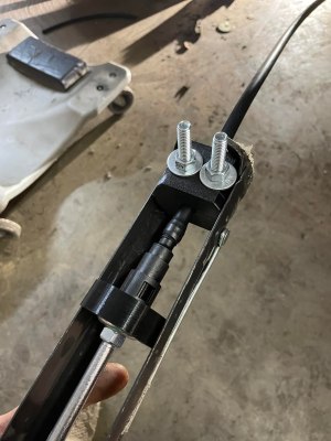
It’s a great tool for cleanly pushing fittings into nylon fuel line.

This build consists of a series of 3D-printed parts that can readily be adapted to a garden-variety caulking gun. First up are a pair of fuel line clamps which are fastened together with nuts and bolts, The nylon fuel line is inserted between these, and the bolts are tightened up to hold the line firmly in place at the end of the caulking gun. The fitting to be installed into the line is then placed on the caulking gun’s plunger. It’s then a simple matter of pulling the trigger on the caulking gun to slowly press the fitting into the nylon line.

It’s a great hack which creates a useful linear press with just a few cents of PETG filament. If you find yourself doing a one-off fuel line job on a modern car, this could be just the tool you need. Parts are available on Thingiverse for those eager to print their own. The design is made for 3/8ths inch line, but could readily be modified or recreated to suit other diameters.

3D-printed tools can be useful in all kinds of ways, even in heavy-duty applications like press tooling. It often doesn’t have the same longevity of traditional metal tooling, but for small one-off jobs, the price saving is often more important than the hardiness of the tooling itself. If you’ve whipped up some great 3D-printed tools of your own, don’t hesitate to drop us a line!

Hackaday Prize 2022: Vintagephone Links The Past To The Present (and Future)

Brrrrrrrring! Movies and TV are one thing, but the siren song of a rotary phone ringing in the same room as you is one of those sounds you carry forever. Not old enough to remember them? Ah, so what? There’s no reason to lose these beauties to the annals of time. In fact, we think more old phones should be repurposed so that present and future generations can experience the finger-hookin’ good time of the rotary dial and the high-voltage peal of those brass bells.

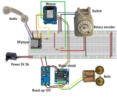
That’s exactly what [Giulio Pons] has done with Vintagephone — turned a rotary phone into a digital assistant with an analog interface. He’s reused all the good bits like the rotary dial, the bells, the handset, and the hang-up switch and connected them up to a Wemos ESP8266 development board with a mini motor driver shield and a voltage booster to ring the bells.

When it’s all said and done, [Giulio] will be able to set an alarm by dialing in the time, ring a number to get the current time and date, and ring another number to get the weather forecast. Reminds us of our childhood pastime of calling Time and Temperature to get outside verification that time had, in fact, passed inside the house on those boring rainy days.

Follow along with [Giulio] as the Vintagephone comes to life in the logs, which already have some great instructions for doing a similar number to an old phone you may have lying around. You can find the code on GitHub.

Got some old tech lying around? Teach it some new tricks and enter the Reuse, Recycle, Revamp round of the 2022 Hackaday Prize!