Tesla Coil Uses Vintage Tube

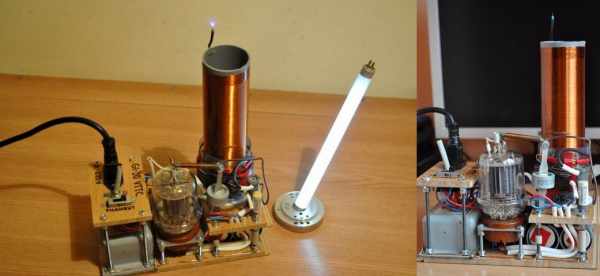
We’ve seen a fair amount of Tesla coil builds, but ones using vacuum tubes are few and far between. Maybe it’s the lack of availability of high power tubes, or a lack of experience working with them among the younger crop of hackers. [Radu Motisan] built a vacuum tube Tesla coil several years back, and only just managed to tip us off recently. Considering it was his first rodeo with vacuum tubes, he seems to have done pretty well — not only did he get good results, he also managed to learn a lot in the process.

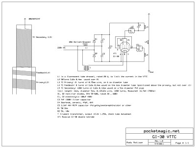
His design is based around a GI-30 medium power dual tetrode. The circuit is a classical Armstrong oscillator with very few parts and ought to be easy to build if you can lay your hands on the tricky parts. The high voltage capacitors may need some scrounging. And of course, one needs to hand-wind the three coils that make up the output transformer.

Getting the turns ratios of the coils right is quite critical in obtaining proper power transfer to the output. This required a fair amount of trial error before [Radu] could get it right.

The use of a 20W fluorescent tubelight ballast to limit the inrush current is a pretty nice idea to prevent nuisance tripping of the breakers. If you’d like to try making one of your own, head over to his blog post where you will find pictures documenting his build in detail. If you do decide to make one, be extremely careful — this circuit has lethal high voltages in addition to the obvious ones, since it operates directly from 220 V utility supply.

Continue reading “Tesla Coil Uses Vintage Tube”

Pedal-Pi, Simple Programmable Guitar Pedal

For several years, [Ray] and [Anna], the team behind ElectroSmash, have been smashing audio electronics and churning out some sweet DIY audio gear. This time around, they’ve built Pedal-Pi — a simple programmable guitar pedal based around the Raspberry-Pi Zero. It is aimed at hackers, programmers and musicians who want to experiment with sounds and learn about digital audio. A lot of effort has gone in to documenting the whole project. Circuit analysis, a detailed BoM, programming, assembly and background information on related topics are all covered on their Forum.

The hardware is split in to three parts. On the input, a MCP6002 rail-to-rail op-amp amplifies and filters the analog waveform and then a MCP3202 ADC digitizes it to a 12-bit signal. The Pi-Zero then does all of the DSP, creating effects such as distortion, fuzz, delay, echo and tremolo among others. The Pi-Zero generates a dual PWM signal, which is combined and filtered before being presented at the output. The design is all through hole and the handy assembly guide can be useful for novices during assembly.  The code examples include a large number of pedal effects, and if you are familiar with C, then there’s enough information available to help you write your own effects.

Even if you don’t plan on building one, technical background such as the Basics of Audio DSP in C for Raspberry Pi Zero, Using MCP3202 ADC with Raspberry Pi Zero and PWM Audio on Raspberry Pi Zero ought to make for interesting reading. Check out the video after the break detailing the build.

If you’d like to check out some of their earlier work, check out 1WAMP, an Open Hardware Guitar Amplifier and pedalSHIELD, an opensource Arduino Guitar Pedal.

Continue reading “Pedal-Pi, Simple Programmable Guitar Pedal”

Open Source High Power EV Motor Controller

For anyone with interest in electric vehicles, especially drives and control systems for EV’s, the Endless-Sphere forum is the place to frequent. It’s full of some amazing projects covering electric skateboards to cars and everything in between. [Marcos Chaparro] recently posted details of his controller project — the VESC-controller, an open source controller capable of driving motors up to 200 hp.

[Marcos]’s controller is a fork of the VESC by [Benjamin Vedder] who has an almost cult following among the forum for “creating something that all DIY electric skateboard builders have been longing for, an open source, highly programmable, high voltage, reliable speed controller to use in DIY eboard projects”. We’ve covered several VESC projects here at Hackaday.

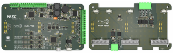
While [Vedder]’s controller is aimed at low power applications such as skate board motors, [Marcos]’s version amps it up several notches. It uses 600 V 600 A IGBT modules and 460 A current sensors capable of powering BLDC motors up to 150 kW. Since the control logic is seperated from the gate drivers and IGBT’s, it’s possible to adapt it for high power applications. All design files are available on the Github repository. The feature list of this amazing build is so long, it’s best to head over to the forum to check out the nitty-gritty details. And [Marcos] is already thinking about removing all the analog sensing in favour of using voltage and current sensors with digital outputs for the next revision. He reckons using a FPGA plus flash memory can replace a big chunk of the analog parts from the bill of materials. This would eliminate tolerance, drift and noise issues associated with the analog parts.

[Marcos] is also working on refining a reference design for a power interface board that includes gate drivers, power mosfets, DC link and differential voltage/current sensing. Design files for this interface board are available from his GitHub repo too. According to [Marcos], with better sensors and a beefier power stage, the same control board should work for motors in excess of 500 hp. Check out the video after the break showing the VESC-controller being put through its paces for an initial trial.

Continue reading “Open Source High Power EV Motor Controller”

Super Simple Controller For Motorcycle LED Lights

For automobiles, especially motorcycles, auxiliary lighting that augments the headlights can be quite useful, particularly when you need to drive/ride through foggy conditions and poorly lit or unlit roads and dirt tracks. Most primary lighting on vehicles still relies on tungsten filament lamps which have very poor efficiency. The availability of cheap, high-efficiency LED modules helps add additional lighting to the vehicle without adding a lot of burden on the electrical supply. If you want to add brightness control, you need to either buy a dimmer module, or roll your own. [PatH] from WhiskeyTangoHotel choose the latter route, and built a super simple LED controller for his KLR650 bike.

He chose a commonly available 18 W light bar module containing six 3 W LEDs. He then decided to build a microcontroller based dimmer to offer 33%, 50% and 100% intensities. And since more code wasn’t going to cost him anything extra, he added breathing and strobe modes. The hardware is as barebones as possible, consisting of an Arduino Nano, linear regulator, power MOSFET and control switch, with a few discretes thrown in. The handlebar mounted control switch is a generic motorcycle accessory that has two push buttons (horn, headlight) and a slide switch (turn indicators). One cycles through the various brightness modes on the pushbutton, while the slide switch activates the Strobe function. A status indicator LED is wired up to the Nano and installed on the handlebar control switch. It provides coded flashes to indicate the selected mode.

It’s a pity that the “breathing” effect is covered under a patent, at least for the next couple of years, so be careful if you plan to use that mode while on the road. And the Strobe mode — please don’t use it — like, Ever. It’s possible to induce a seizure which won’t be nice for everyone involved. Unless you are in a dire emergency and need to attract someone’s attention for help.

Continue reading “Super Simple Controller For Motorcycle LED Lights”

PocketCHIP As A Hardware Hacker’s Terminal

Conferences these days can be tricky places to be at – especially hardware and hacker cons. If you aren’t the one doing the hacking, then you can be sure your devices are being probed, pinged and possibly, hacked. It certainly isn’t the place to bring your precious laptop. Besides, as the day wears on and your feet start aching, regular laptops start feeling bigger and heavier. What you need is a burner laptop – one that is lightweight, cheap and that you don’t mind getting hacked. [dalmoz] wrote a short, to-the-point, tutorial on making use of PocketCHIP as a hardware-hacker’s best friend when it comes to UART connections. It’s also handy to use as a stand alone serial monitor for your projects without having to dedicate a USB port and screen real estate.

The PocketCHIP is a dock for the C.H.I.P. microcomputer and adds a LED backlit touchscreen display, QWERTY keyboard and LiPo battery in a lightweight, molded case. For $70, you get a 1 GHz ARM v7 processor, 512MB RAM, Mali 400 GPU, WiFi and Bluetooth. It’s light enough to be hung around your neck via its lanyard slot. And all of the GPIO pins are conveniently broken out, including the UART pins. Right now, it’s in the hands of Kickstarter backers, but the Next Thing Co website indicates availability sometime this month.

On the hardware side, all you need to do is add header pins to TX, RX and GND (and maybe 5 V and 3 V if required) on the PocketCHIP GPIO header and you’re good to go. On the software side, things are equally easy. The UART pins are meant to provide debug access to the CHIP itself and need to be released from internal duty. Once the UART port is identified, a single terminal command frees its status as a debugging interface. After that, use any terminal emulator – [dalmoz] recommends Minicom – and you’re all set. In the unlikely event that all you have is an Arduino lying around, [dalmoz] posted a simple sketch that can be used to make sure you have it working. Great hacking tip, ’cause it is as simple as it gets. If you’d like to know more about the CHIP project, check out its documentation and Github repository – it’s all open source.

Hackaday Prize Entry: Mini DRO For A Lathe

A manual lathe has dial wheels to control the feed of the main carriage and the cross slide to help take cuts on the workpiece. These feed wheels always have some backlash and require frequent resetting of the “zero”. The usual process would be to take measurements on the workpiece with either a vernier caliper or a micrometer at intervals which requires stopping the machine, adding up to increased machine time. The addition of a digital readout not only simplifies the process, but also reduces machining time substantially. Since the DRO magnetic strips are directly attached to the cross slide, the effects of backlash are mitigated.

[Igor] has just such a manual lathe and built his own mini DRO unit from scratch a couple of years back. Most DRO’s have encoder strips and sensors attached to the cross slide with a larger display unit attached separately on a stalk, with wires running between the two. [Igor] kept things simple by building a unit that fit within the space constraints he had. His unit consists of just two sensor modules – each attached directly to the slide. The main unit houses a linear hall sensor, electronics, buttons, a small LCD and batteries. The second axis unit houses just the sensor with a cable connecting it to the main unit for data and power. At the heart of the system is a pair of NSE-5310 linear hall sensor encoder chips. These work in conjunction with multipole magnetic strips. The encoder provides a 12-bit output, and the magnetic strips have poles spaced 2 mm apart. This translates to a theoretical resolution of almost 0.5 microns, but of course, the machine mechanics limit the actual results. The encoder chips talk to an ATtiny2313 over the I2C bus. Three buttons and the power supply round-up the hardware. To run it off a single 1.5 V rechargeable battery, [Igor] used a boost converter to get 3.3 V. The 5 V needed for the LCD is obtained by a voltage doubler connected to a PWM output from the microcontroller and regulated by a Zener diode. The second sensor unit connects via a TRRS 3.5 mm socket.

He added a Bluetooth module as an after thought, but ran out of GPIO pins as well as program space and had to get creative to make it work. The plan was to transmit the data to an Android tablet which would work as a large, remote, wireless display. He never did use that feature though, being satisfied with the small LCD display. There’s several things that went wrong in the build, and if he were to replicate the project again, several changes and improvements would help. So if anyone plans on doing something similar, do check up [Igor]’s project logs first.

Hackaday Prize Entry: Vibhear

Hearing impairment, either partial or total, is a serious problem afflicting a large number of people. Almost 5% of the global population has some form of hearing disorder. For those affected by this disability from birth, it further impacts the development of language and speech abilities. In recent years, cochlear implants are increasingly being used to address this problem. These implants consist of two parts – the receiver and electrode array are implanted under the skin near the ear (with the electrode array terminating inside the Cochlea), while the microphone, electronics, transmitter and power source are attached on the outside. Often, the external unit has to be removed – for example, when the person needs to sleep. This is particularly so in the case of young children. The external unit is fairly large compared to their head and causes discomfort during sleep. And parents are worried that the expensive device could get damaged when the child is sleeping. This leads to the alarming situation where the child is asleep and has no audio sensory inputs being received from the surroundings. Not only can they not hear morning alarms, but also cannot react when there is an emergency situation such as a smoke alarm going off.

[Srdjan Pavlovic] came across this problem first hand when he visited his friend and learned about their six-year-old son with hearing loss since birth. The parents said their child will not be disturbed by loud noises at night since the external unit of his cochlear implant is removed each night. [Srdjan] then started work on building the Vibhear – an assistive hearing device to be used when the main hearing aid is removed or not working. It is a low-cost arm-band that provides a vibratory signal in response to high ambient noises.

The main components are a microphone, amplifier, microcontroller and vibration motor powered by a LiPo battery through a boost converter/charger. An RTC module allows setting up daily wake up alarms. It’s currently prototyped around the Arduino, but the next iteration will use a specialized DSP which can be programmed to perform signal processing operations on input sound. This will allow identification of specific sounds such as car horns, barking dogs, smoke alarms or emergency sirens.

[Srdjan] is in the process of choosing components for his next iteration, so if you have any recommendations to help him choose the microcontroller, power supply controller or other parts, do let him know via comments below.