El Cheapo Electric Screwdriver

If you have a few hobby servos lying around, here’s a hack that let’s you recycle them and put them to good use. [Kedar Nimbalkar] took a micro servo and converted it into an electric screwdriver. It is simple enough to deserve a short video showing how he did it.

He starts by opening up a 9G micro servo and removing the electronics. All that’s needed is the DC motor and the gears. The two motor wires go directly to the battery via a polarity reversal switch to allow the motor to turn in both directions. The servo horn is cut to size so that it is a tight fit inside the screwdriver socket. A liberal amount of glue is used to make sure it stays in place. The horn is then attached to the modified servo, ready to take interchangeable bits. One last mod before closing up the servo is to convert it to continuous rotation by cutting off the stopper in the drive gear.

He built the power supply from scratch, using a 18650 Li-Po battery, a 5V USB charger, a DPDT switch to allow direction control and a push button to actuate the screw driver. A pair of LED’s connected back to back serve as direction indicators as well as some local illumination.

There’s lot’s of scope to improvise and do everything differently, but the basic premise of using unused servos for a handy electric screwdriver is pretty neat.

Continue reading “El Cheapo Electric Screwdriver”

Developed On Hackaday – It’s A Badge. No, It’s The HaDge

Sometime back, we announced start of a new project under the “Developed on Hackaday” series – a Badge for the Hackaday community. At its core, this badge is a single node in an Internet of Badges. At every event this badge is deployed at, a Hackaday Sub-Etha mesh network will be created, and each badge will be able to transmit and receive messages from other badge wearers. There are plans for an Sub-Etha to Internet gateway, so even if badge wearers are on the other side of the world, they’re still connected through the HaDge network.

Things have been moving along quickly, so I thought of doing a quick round-up and share progress with the community. First off, it has a name. HaDge, as in HackaDay Badge. Our objectives up until now were to set up a team, name the project, set up repositories and lock down on a working bill of materials. Within a few weeks, we’ve got all of that tied down. The HaDge group chat channel has been super active, and everyone’s been pitching in with ideas and suggestions. A spreadsheet seemed like a good idea – it let everyone add in their suggestions regarding candidate parts, create a feature list and then talk about it on the channel.

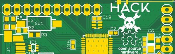
We realized early on that building the hardware is going to take some time. So in the interim, we need a dev kit platform to get in to the hands of the software developers so they can start working on the smarts that will power the HaDge. [Michele Perla] had already built JACK (Just another Cortex kit) – a development kit powered by the Atmel SAM D21. It’s pretty bare bone with just the bare minimum of parts to make it work while keeping an eye on reliability. The microcontroller+radio on the HaDge is the Atmel SAM R21 – a close relative of the D21, so it made sense to respin the JACK and create HACK (Hackaday Cortex kit) – a development kit powered by the Atmel SAM R21 that is going to be used as the core of the HaDge. [Michele] has worked hard single-handedly to complete the design and it is now ready to go for PCB fabrication soon. We are just awaiting some feedback and review of the Antenna part of the design. None of us on the hardware team have a strong RF-fu so we don’t want to make an avoidable mistake. If you’d like to review and help vet the HACK design, grab the design files from the github repo and let us know.

Once HACK board layout is cleared for fabrication, we’ll work on building kits that can be sent out to the software folks. We will also be working on porting the HACK design in to KiCad and this is something I have already stared work on. I started by using the neat Eagle2KiCad conversion tool by [LachlanA]. It’s not perfect, but it does reduce the work involved in porting over from Eagle to Kicad. Once that is done, hardware development for the actual HaDge will see some progress – keep a watch on the project page.

CNC’ed Business Card

Hobby CNC mills have made rapid prototyping easier and faster for hackers. One really useful application is quickly fabricating your own milled PCB’s. [proto logical] built a Reference PCB Business Card using his CNC mill after repeatedly coming across other hackers who were not too convinced about the capabilities of CNC mills in routing PCB’s (also referred to as isolation milling). He thought of making a business card sized reference PCB to show around when he bumps into such folks.

To keep it useful, he included inch and centimetre scales, 0.1″ grid of holes, reference track widths from 16 mil to 66 mil, a few common drill holes and vias and some SMD foot prints. The single sided board is 50 mil thick, so it doesn’t bulk up his wallet. He’s posted the Eagle board file (direct download) and G-code (text file) for those interested in milling their own reference boards. The idea isn’t new – it’s been tried several times in different form factors in the past, generally using more traditional techniques. [proto logical] got inspiration from [Rohit Gupta’s] TinkerRule – The Maker’s Swiss Army Knife. Then there’s the very popular uRuler made by [Dave Jones] of EEVBlog fame. If you have any suggestions on improving the design, chime in with comments here.

Thanks to [ACG] for sending in this tip that he dug up while looking for CNC routed PCB’s.

Simple USB Power Meter

The USB interface is being increasingly used as a power supply and charging port for all kinds of devices, besides data transfer. A meter to measure the electrical parameters of devices connected to a USB socket or charger would be handy on any hacker workbench. The folks at [electro-labs] designed this simple USB power meter which does just that.

The device measures voltage and current and displays them, along with the calculated power, on the small 0.5″ OLED display. The circuit is built around an ATmega328. To keep the board size small, and reduce component count, the microcontroller is run off its internal 8MHz clock. A low-resistance shunt provides current sensing which is amplified by the LT6106 a high side current sense amplifier before being fed to the 10 bit analog port of the ATmega. A MCP1525 precision voltage reference provides 2.5V to the Analog reference pin of the microcontroller, resulting in a 2.44mV resolution. Voltage measurement is via a resistive divider that has a range of up to 6V. An Arduino sketch reads voltage and current data on the analog ports and displays measurements on the display. The measured data is averaged to filter out noise.

The OLED display has a SPI interface and requires the u8glib library. The project uses all SMD parts, but is fairly easy to assemble by hand and could be a nice starter project if you want to wet your feet on surface mount assembly techniques. It’s designed using SolaPCB EDA software, and the source files for schematic and board layout are available as a ZIP archive. Download the BoM and Arduino code and you have everything needed to build this nifty device.

Thanks to [Abdulgafur] for sending in this tip. And if you are looking for a more comprehensive solution, check the awesome Friedcircuits USB Tester which we reviewed earlier and is available in the Hackaday Store.

Hello RAMPS, Meet ESP8266

The proliferation of  DIY 3D printers has been helped in large measure by the awesome open-source RepRap project. A major part of this project is the RAMPS board – a single control board / shield to which all of the other parts of the printer can be easily hooked up. A USB connection to a computer is the usual link of choice, unless the RAMPS board has the SD-Card option to allow the 3D printer to operate untethered. [Chetan Patil] from CreatorBot built a breakout board to help attach either the ESP8266 WiFi or the HC-05 Bluetooth module to the Aux-1 header on the RAMPS board. This lets him stream G-code to the printer and allow remote control and monitoring.

While the cheap ESP8266 modules are the current flavor of the season with Hackers, getting them to work can be quite a hair tearing exercise. So [Chetan] did some hacking to figure out the tool chain for developing on the ESP module and found that LUA API from NodeMcu would be a good start. The breakout board is nothing more than a few headers for the ESP8266, the HC-05 and the Aux-1 connections, with a few resistors, a switch to set boot loader mode and a 3.3V regulator. If you’re new to the ESP8266, use this quick, handy, guide by [Peter Jennings] to get started with the NodeMCU and Lualoader. [Chetan]’s code for flashing on the ESP8266, along with the Eagle board design files are available via his Github repo. Just flash the code to the ESP8266 and you’re ready to go.

One gotcha to be aware of is to plug in the ESP module after the printer has booted up. Otherwise the initial communication from the ESP module causes the printer to lock up. We are sure this is something that can be taken care of with an improved breakout board design. Maybe use a digital signal from the Arduino Mega on the RAMPS board to keep the ESP module disabled for a while during start up, perhaps? The video after the break gives a short overview of the hack.

Continue reading “Hello RAMPS, Meet ESP8266”

Developed On Hackaday: Let’s Build An Electronic Hackaday Badge

We’re going to build an electronic Hackaday Badge, and by “we”, I mean Hackaday community members who are passionate about the project.

I’ll be leading the charge. I had a great learning experience the last time I helped design the e-paper badge for the 2013 Open Hardware Summit, and hope to learn a lot along the way this time too. Since then, Badges have come a long way – at cons like DEFCON, LayerONE, Shmoocon, The Next Hope, Open Hardware Summit, The EMF, SAINTCON, SXSW Create, The Last Hope, TROOPERS11, ZaCon V and of course the rad1o from this year’s CCCamp. Word is that this year’s Open Hardware Summit badge is going to be pretty kickass too. So, we have some very big shoes to fill. But this doesn’t have to be about “my badge is better than yours”. And this badge isn’t meant to be specific to any single con or event. So what does the Badge do, then? “It’s a physical extension of the hackaday.io community, made specifically for hacker gatherings of all types and sizes.”

Continue reading “Developed On Hackaday: Let’s Build An Electronic Hackaday Badge”

Junked Inspection Camera Given 15-Year Face-lift With Raspberry Pi

The nice thing with having a hacker cred is that family and friends are always on the lookout for stuff they think might be useful to you. [Craig Hollabaugh]’s son-in-law found an inspection camera and thought it would be handy for his hobby work. The MagniSight Explorer was first introduced in 2001. It is good for surface mount board work and inspection, except that its analog 480p video is quite dated by today’s standards. So [Craig] upgraded it for crystal clear 1080P/30 video and 5 megapixel images using a $35 Raspberry Pi 2 and a $26 Raspberry Pi Camera Module. After the upgrade, the unit is now a great tool for SMT rework.

There’s not a lot to the upgrade, but [Craig] gives a nice rundown in the 15 minute video of the MagniSight’s internals. He shows us the original analog camera module and its video card, which is able to do some additional processing like black and white output and reverse video (negative). As he mentions, it would be easy for him to do the same via software on the Raspberry Pi. A video camera lens takes care of magnification and two shafts coupled to it via flat belts (rubber bands?) take care of zoom and focus. A front coated mirror angled 45 degrees in front of the lens turns the optical path 90 degrees to allow the lens/camera to “look down”. After experimenting a bit to find the correct focal spot behind the lens unit for the Raspberry Pi camera, he covered the camera module with insulation tape and then just glued it to the old camera mount. After hooking it up to an HDMI monitor, the results are quite nice and he reckons he can easily work with components down to 0402 in size.

He’s got a couple of more upgrades in mind to make the system even better. He plans to replace the existing compact fluorescent lamps with a string of LED’s which will provide more uniform illumination. Plus, he can control their brightness, and selectively turn them on or off to get the optimum lighting. The other interesting upgrade would be to add stepper motors to the X-Y translation stage and automate their movement. After looking up a board file and its BoM, he may even be able to search for a part designator and move the stage to bring the part into focus.

Continue reading “Junked Inspection Camera Given 15-Year Face-lift With Raspberry Pi”