Smallest Discrete Transistor 555 Timer

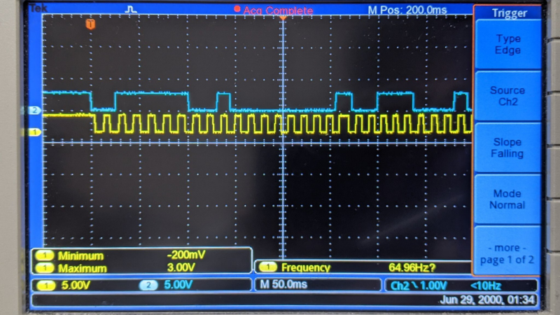
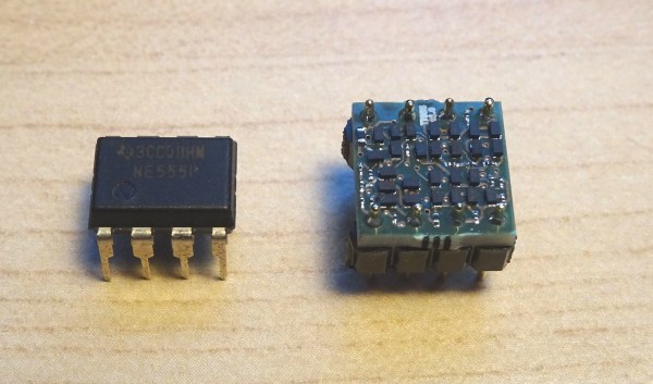
Over at Tiny Transistor labs, [Robo] took it upon himself to reproduce the classic 555 timer in discrete transistor form. For bonus points, he also managed to put it in a package that’s the same basic size, pin compatible with, and a plug-in replacement for the original. The first task was deciding which 555 circuit to implement. He examined a handful of different implementations — and by examined, we mean dissected them and studied the die circuitry under a microscope. In the end, he went with Hans Camenzind’s original circuit, both as a tribute and because it used the fewest transistors — a point which helped manage the final size, which is only a little bit bigger than the IC!

Speaking of sizes, have you ever soldered an EIA 01005 resistor? We agree with [mbedded.ninja] who wrote on a post about standard chip resistor sizes, the 01005 is a “ridiculously small chip package that can barely be seen by the naked eye.”  It is 16 thou x 8 thou (0.4 mm x 0.2 mm) in size, and despite its name and placement in the Imperial series, it is not half the size of an 0201. The transistors are your standard 2N3904 / 2N3906, but purchased in a not-so-standard DFN (Dual Flat Pack, No Leads). We might think a 1.0 x 0.6 mm component as small, but compared to its neighboring resistors in this circuit, it’s huge.

[Robo] has done this kind of project before, most recently making a discrete recreation of of the classic 741 op-amp. We covered a similar, but larger, discrete 555 timer project back in 2011. If you want to go really big-scale with your own reproduction project, check out the MOnSter 6502 from five years ago for further inspiration. Thanks to [Lucas] for the tip.

Artwork Spans Fifty Years Of Display Technology

Swiss artist and designer [Jürg Lehni] was commissioned to create an artwork called Four Transitions which has been installed in the HeK (House of electronics Arts) in Basel. This piece visually depicts the changes in technologies used by public information displays, such as those in airports and train stations. As the title of the installation suggests, four different technologies are represented:

  • Flip-Dot, early 1960s, 15 each 7 x 7 modules arrayed into a 21 x 35 pixel panel
  • LCD, 1970s and 1980s, two each 36 x 52 modules arrayed into 52 x 76 pixel panel
  • LED, 2000s, six each 16 x 16 RGB modules arrayed into a 32 x 48 pixel panel
  • TFT, current, one 24 inch module, 1200 x 1920 pixel panel

The final work is quite striking, but equally interesting is the summary of the the design and construction process that [Jürg] provides on Twitter. We hope he expands this into a future, more detailed writeup — if only to learn about reverse engineering the 20 year old LCD controller whose designer was in retirement. His tweets also gives us a tantalizing glimpse into the software, controllers, and interconnections used to drive all these displays. There is quite a lot of interesting engineering going on in the background, and we look forward to future documentation from [Jürg].

You may recognize [Jürg] as the creator of Hektor, a graffiti output device from 2002 which we’ve referenced over the years in Hackaday. Check out the short video below of the displays in operation, and be sure to unmute the volume so you can listen to the satisfying sound of 735 flip-dots changing state. [Jürg] also gives in interview about the project in the second video below. Thanks to [Niklas Roy] for sending in the tip about this most interesting exhibition.

Continue reading “Artwork Spans Fifty Years Of Display Technology”

Improved Graphics-to-Drawing Tablet Conversion

[Akaki Kuumeri] had an old Wacom Intuos digitizing graphics tablet collecting dust, and figured out how to non-destructively transform it into a drawing tablet. He was inspired by an old Hackaday post of a similar hack, but it required literally hacking a big hole into your Wacom tablet. Not wanting to permanently ruin the Wacom tablet,  [Akaki] instead designed a 3D printed frame which he holds in place with a pair of straps. The design files are available on Thingiverse. He names the project, incorrectly as he later points out, WacomOLED (it rhymes with guacamole, we think).

As for the screen, he buys an old third-generation iPad and removes its Retina display panel and the foil backing, which would otherwise block the stylus’s connection to the tablet. Toss in an HDMI driver board to connect the display to your computer, and presto — you have made your own a drawing tablet. Even if you don’t need a drawing tablet, [Akaki]’s hack is still interesting, if only to remind us that we can put custom HDMI displays into any project for $65 using this technique.

In the end, [Akaki] notes that unless you already have a non-graphical digitizing tablet laying around, it’s probably cheaper to just buy a iPad. This is not [Akaki]’s first go at user input devices — we wrote about his Smash Brothers game controller and flight controller yoke project last year.

Do any of you use a graphics tablet in your day to day workflow? Let us know in the comments below.

Continue reading “Improved Graphics-to-Drawing Tablet Conversion”

VME Reverse Engineering

With some free time on his hands waiting for delayed parts to arrive, [Rik] set out to reverse engineer an old VME system he had acquired. VMEbus computers are based on the standard Eurocard PCB format, which defines a wide range of card sizes — the most common being 6U height like [Rik]’s system. They usually consist of a rack-mounted card cage with a passive backplane. Originally, Motorola 68000-based CPU cards were used in VMEbus systems, but any processor could be used as long as you provided the right signals and timings to the system bus. Eurocard systems are less common these days, but are still used in some applications. In fact, if you’re into synthesizers, you may be using Eurocards today — the Eurorack standard is based on the standard 3U card size.

Back to [Rik]’s project, he had no idea what this system was nor how to use it. A bit of probing around and he found two UARTs, a system monitor, and a way to load and dump S-record files. He documents the process quite well, as the internal layout and memory map of the system is unlocked piece by piece. We also like his method of instrumenting the VMEbus signals — logic analyzers are so small today, you can just mount one inside the rack.

Spoiler alert: [Rik] succeeds in mapping out the memory, writes some small programs in 68k assembly language, and even builds his own LED accessory card so he can blink some lights (as one must do).

We wrote about modularity recently, and VMEbus + Eurocard systems are good examples of modular design. You could quickly put together a robust assembly using entirely off-the-shelf cards, or mix in your own custom cards. But technology advancements in clock speeds and miniaturization have made these card cage, passive backplane systems less and less relevant today. Do any of you still use the VMEbus, or have you designed with them in the past? Let us know down in the comments below.

Synth Gains Plug And Play Analog MUX

High school computer engineering teacher [Andy Birch] kept losing track of I/O pins on his home-built synth, so he made a custom plug and play addressable MUX system to solve the problem. [Andy]’s synth is based on the Teensy microcontroller, and he was already using CMOS analog 8:1 multiplexer chips (CD4051) to give him more I/O pins. But I/O pin expansion means that now there are more I/O pins to forget. Did I hook up that pitch potentiometer on U3 pin 13 or was it U10 pin 2?

He proceeds to design an addressing system for each I/O card using three bits (expandable to four) supporting eight cards, with a maximum of 16 possible in the future. Since each card may not use all eight signals, each card can tell the Teensy how many signals it has. [Andy] does his address decoding on each card using OR and XOR gates. We would have considered using a single 74HC85 four-bit magnitude comparator instead. That would require only one chip instead of two, but would deprive his students of the opportunity to learn gate level address decoding.

When seeing the term “I/O card”, you may be fooled like we were into thinking this was using PCBs and some kind of motherboard. [Andy]’s I/O cards are actually solderless breadboards mounted on the back of the synth control panel. We really like his bus technique — he removes the power strip sections from several breadboards and repurposes them as address and data buses. Check out the thorough documentation that [Andy] has prepared, and let us know if you have ever designed your own plug and play method for a project in the comments below.

[Ed Note: We love us some muxes!]

I/O Cards — Note the use of Power Strip Bars as Data / Address Buses


Teaching A USBasp Programmer To Speak TPI

Last Fall [Kevin] wanted to program some newer TPI-only AVRs using an old USBasp he had kicking around his lab. Finding an “odd famine of information” and “forums filled with incorrect information and schematics”, he decided to set the record straight and document things correctly. He sleuthed out the details and succeeded in reprogramming the USBasp, although he did end up buying a second one in the process.

Designers who use AVR microcontrollers have no shortage of programming interfaces — we count at least five different methods: ISP/SPI, JTAG, TPI, PDI, and UPDI. We’re not sure whether this is variety is good or bad, but it is what it is. [Kevin] discovers that for the particular family of Attiny devices he is using, the ATtiny20, TPI is the only option available.

While he normally builds his designs around ARM Cortex-M chips, [Kevin] needed some glue logic and decided to go with an ATtiny20 despite its unique programming requirements. He observes that the price of the ATtiny20, $0.53 last Fall, was cheaper than the equivalent logic gates he needed. This particular chip is also quite small — only 3 mm square (a 20-pin VQFN). We would prefer not to use different MCUs and tool chains on a single board, but sometimes the convenience and economics steer the design in that direction.

If you’re not familiar with the USBasp, our own [Mike Szczys] covered the breaking story over ten years ago. And if you have a lot of free time on your hands, ditch all these nicely packaged solutions and program your chips using an old USB Hub and a 74HCT00 NAND gate as described in this bizarre hack by Teensy developer [Paul Stoffregen].

I2C Paper Tape Reader Is Not What You Think

We’re not quite sure what drove the development of this project, but [shapoco] has put together an intriguing device that reads I2C signals (Japanese Twitter link) which have been printed as black and white rectangles on paper tape. He wrote a program that prints an I2C byte stream onto strips containing the SCL and SDA signal patterns. Once printed, you cut the strips from the paper and glue them together into one long piece, making a complete message — in this case, commands to a small LCD screen that will display the phrase “Hello, Tape I2C”.

We’re not sure exactly sure what’s inside that rectangular widget epoxied to the bottom of that perf board through which the tape passes. But clearly, it must contain a pair of LEDs to illuminate the tape and a pair of sensors to detect the reflection off the tape (looking at the wiring, it seems unlikely that anything is mounted underneath the tape). According to one machine-translated Twitter message, detection is done using a Schmitt trigger made from an LM393 comparator with hysteresis (see this TI app note for a review of this type of circuit). Here’s a scope capture of the resulting signals. [Shapoco] notes that the circuit can operate much faster — the tape is being pulled slowly in the video to make it easier to see.

This is not [shapoco]’s first experiment in optical I2C communications. Check out the second video down below where he’s reading I2C signals from a computer’s display. One person tweeted about how software source code was sometimes printed optically in old Byte magazines many years ago, a topic we talked about in Hackaday Podcast #049 last year when discussing Cauzin strips.

Besides just being cool, and possibly helpful as an educational device, does this technique have any real-world applications these days? Let us know your thoughts in the comment section below. Thanks to [Manawyrm] for sending us this tip.

Continue reading “I2C Paper Tape Reader Is Not What You Think”