We remember going to grandfather’s garage. There he would be, his tobacco pipe clenched between his teeth, wisps of smoke trailing into the air around him as he focused, bent over another of his creations. Inside of a simple glass bottle was something impossible. Carefully, ever so carefully, he would use his custom tools to twist wire. He would carefully place each lead. Eventually when the time was right he would solder. Finally he’d place it on the shelf next to the others, an LED matrix in a bottle.
Well, maybe not, but [Mariko Kosaka]’s father [Kimio Kosaka] has done it. In order to build the matrix, he needed tools that could reach inside the mouth of the bottle without taking up too much space to allow for precise movement. To do this he bent, brazed, twisted, and filed piano wire into tools that are quite beautiful by themselves. These were used to carefully bend and position the LEDs, wires, and other components inside the bottle.
Once the part was ready, he used a modified Hakko soldering iron to do the final combination. We wonder if he even had to be careful to solder quickly so as not to build up a residue on the inside of the bottle? The electronics are all contained inside the bottle. One of the bottles contained another impressive creation of his: an entire Arduino with only wire, dubbed the Arduino Skeleton. Batteries are attached to the cork so when the power runs low it can be removed and replaced without disturbing the creation.
It’s a ridiculous labor of love, and naturally, we love it. There’s a video of it in operation as well as one with him showing how it was done which is visible after the break. He showed them off at the Tokyo Maker Faire where they were surely a hit.
I think the restaurant is really close now… CC: E. Broeks
The best way to pull off this deception: tell your significant other that you’d want nothing more than a romantic week in Paris. Arrive in Paris, stash your bags, and then take either the number three or eleven Metro. When you get to the station that looks like the inside of a giant steam engine, Arts et Métiers, get out. You’re now ten Euros away from one of the coolest museums a hacker could visit.
A significant portion of modern science’s beginnings is sitting in the Musée, polished and beautiful. Most of them are housed in cabinets so old they’re part of the exhibit. Now, the Henry Ford museum in Detroit Michigan is a monument to industrialization, and cool in its own right, but it leaves some questions unanswered. We’re all spoiled by desktop CNCs, precision measurement tools for pennies, and more. How did we get here? How did they measure a shaft or turn a screw before precision digital micrometers? What did early automation look like? Early construction?
Also did I mention it has Foucault’s Pendulum? You know, the one that finally convinced everyone that the Earth rotated around an axis? No big deal.
The museum has a few permanent exhibits: instruments scientifique, matériaux, construction, communication, énergie, mécanique et transports.
What kind of basic museum would have just one example of Pascal’s work? CC: Anton Lefterov
Instruments Scientifiques was one of my favorites. Not only did it include old scientific instruments, it had sections containing some of the original experiments in optics, computation, and more. For example you can see not just one but a few original examples of Pascal’s Pascaline, arguably the first mechanical calculators in the modern era to be used by the layman for every day calculation, signed by Pascal. It’s also worth noting just how incredible the workmanship of these tools are. They’re beautiful.
Matériaux was initially a disappointment as I entered it from the wrong end. For me it started of with a tragically boring and simplistic display on recycling materials designed primarily to torture children on field trips. Luckily it quickly ramped into a fascinating display on materials manufacturing technology. How did we go from hand looms to fully automated Jacquard looms (of which you can see some of the first examples) to our modern day robotic looms? How did ceramic evolve? What was early steelmaking like? It’s very cool and models are all in beautiful condition.
It reeked of copper, machine oil, and phenolics. They just don’t make computers like they used to.
By the time I got to Communication I was reaching the limit of my endurance and also what you can fit into a single day of the museum. It’s a large building. It was packed through many of the early examples of computing, television, and space. There was quite a display of early camera equipment. You could get close enough to some truly massive old computers to smell the still off-gassing phenolics.
Construction held my interest for a long time. It’s not my usual interest, but after living in Paris for a month or so I was absolutely burning with curiosity. How did anyone without a single powered crane or vehicle build so many buildings out of stone? It’s packed for four rooms and two stores from floor to ceiling of beautiful little wood models explaining exactly how.
Énergie was quite cool. It followed the development of steam power for the most part. It started with primitive waterwheels. Moved on to turbines. Then showed the gradual increase in complexity until the the modern day. It had some internal combustion too, but much of that was reserved for the transports section of the museum. It also had some interactive displays to entertain children and Hackaday writers. However they were in desperate need of an oiling and this is by far the most ear-piercingly squeaky exhibit in the whole building.
Mécanique is competing with instruments scientifique as my favorite exhibit. Have you ever wanted to see hundreds of examples of screw machines, old lathes, and the evolution of the milling machine? What about models of the factories that built steam engines or massive wagon wheels. They even had a lathe that belonged to a French king. Apparently he thought metalworking was the way to get in touch with the common people.
Transports was a nice exhibit, but it fell a little short for me since I’d been to the aforementioned Henry Ford museum. However, it covered the history of some of the European automobile manufacturers pretty well. Had a nice section on trains and subways. And even had some models of the ships used in the European Space Agency.
The entrance of the school. Has some original, “flying,” machines. CC: King Boshi
The last exhibit is the museum itself. It’s an historic building. It was originally built as a school for training engineers in 1794 but as the school grew out of it, it slowly transformed into the museum it is today. The architecture is beautiful. It’s adorned in stone and statue like all the French museums. It also has sections cut out in some of the higher storeys of the building so you can see how it was constructed.
Part of its beauty is also related to the school swallowing up the Priory of Saint Martin des Champs (Google translate does a great job if you don’t read French). The Priory is a beautiful old church, founded in 1079. It was home to the last trial by combat the country would see. You can piece together the story between the two pages dedicated to the combatants Jean de Carrouges and Jacques Le Gris.
The muses of agriculture and industry now look over the sanctuary.
The final display in the museum is in the church. It holds Foucault’s pendulum, dangling from the center of the sanctuary. If you get there early enough in the day you may get to watch it knock over a peg or two and prove the rotation for yourself.
Rather than the statues of the saints there are statues of the muses of Industrie and Agriculture. The hall is filled with more exhibits. There are cutaway original automobiles. A model of the Statue of Liberty. A catwalk lets you take a high view of the surroundings. It is also beautiful in and of itself. The church is well maintained and painted in the style original to them.
If you find yourself in Paris with a few hours (or days) to spare I highly recommend this museum. Any technical person would be hard pressed to leave uninspired and unawed by the display. It’s good to get a perspective on the past.
It was quite a surprise to learn that thermite isn’t just rust and aluminum powder, but describes any combination of metal powder, metal oxide, and optionally fuel mixed together in a reactive ratio. [sciencewithscreens] shows us some of the properties of a copper (II) oxide based thermite.
We can only assume he has a thing for copper as an element. After growing his copper crystal it wasn’t long before he followed a winding road of copper based experiments and found himself with a supply of copper (II) oxide after rendering it from common household chemicals. He had two missions for it. The first was to witness an unfettered copper oxide based thermite reaction. Some had assured him it was practically explosive. The other was to attempt refining pure copper using the reaction. That would be pretty cool considering it all started out as an impure blend of laundry detergents and fertilizer.
[Chris Gunawardena] is still holding his breath on Valve and Facebook surprising everyone by open sourcing their top secret VR prototypes. They have some really clever ways to track the exact location and orientation of the big black box they want people to strap to their faces. Until then, though, he decided to take his own stab at the 3D tracking problems they had to solve.
While they used light to perform the localization, he wanted to experiment with using electromagnetic fields to perform the same function. Every phone these days has a magnetometer built in. It’s used to figure out which way is up, but it can also measure the local strength of magnetic fields.
Unfortunately to get really good range on a magnetic field there’s a pesky problem involving inverse square laws. Some 9V batteries in series solved the high current DC voltage source problem and left him with magnetic field powerful enough to be detected almost ten centimeters away by his iPhone’s magnetometer.
As small as this range seems, it ended up being enough for his purposes. Using the existing math and a small iOS app he was able to perform rudimentary localization using EM fields. Pretty cool. He’s not done yet and hopes that a more sensitive magnetometer and a higher voltage power supply with let him achieve greater distances and accuracy in a future iteration.
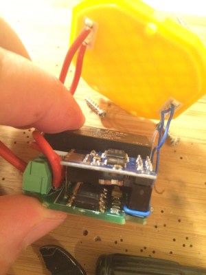
[Hristo Borisov] shows us his clever home automation project, a nicely packaged WiFi switchable wall socket. The ESP8266 has continuously proven itself to be a home automation panacea. Since the ESP8266 is practically a given at this point, the bragging rights have switched over to the skill with which the solution is implemented. By that metric, [Hristo]’s solution is pretty dang nice.
It’s all based around a simple board. An encapsulated power supply converts the 220V offered by the Bulgarian power authorities into two rails of 3.3V and 5V respectively. The 3.3V is used for an ESP8266 whose primary concern is the control of a triac and an RGB LED. The 5V is optional if the user decides to add a shield that needs it. That’s right, your light switches will now have their own shields that decide the complexity of the device.
The core module seen to the right contains the actual board. All it needs is AC on one side and something to switch or control on the other The enclosure is not shown (only the lid with the shield connectors is seen) but can be printed in a form factor that includes a cord to plug into an outlet, or with a metal flange to attach to an electrical box in the wall. The modules that mate with the core are also nicely packaged in a 3D printed shield. For example, to convert a lamp to wireless control, you use a shield with a power socket on it. To convert a light switch, use the control module that has a box flange and then any number of custom switch and display shields can be hot swapped on it.
It’s all controllable from command line, webpage, and even an iOS app; all of it is available on his GitHub. We’d love to hear your take on safety, modularity, and overall system design. We think [Hristo] has built a better light switch!
Practically any combination of motor and gearbox can be mathematically arranged to fit all sorts of problems. You could lift a crane with a pager motor, it just might take a few hundred years. However, figuring out exactly what ratio you need can feel bit backwards the first time you have to do it.
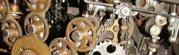
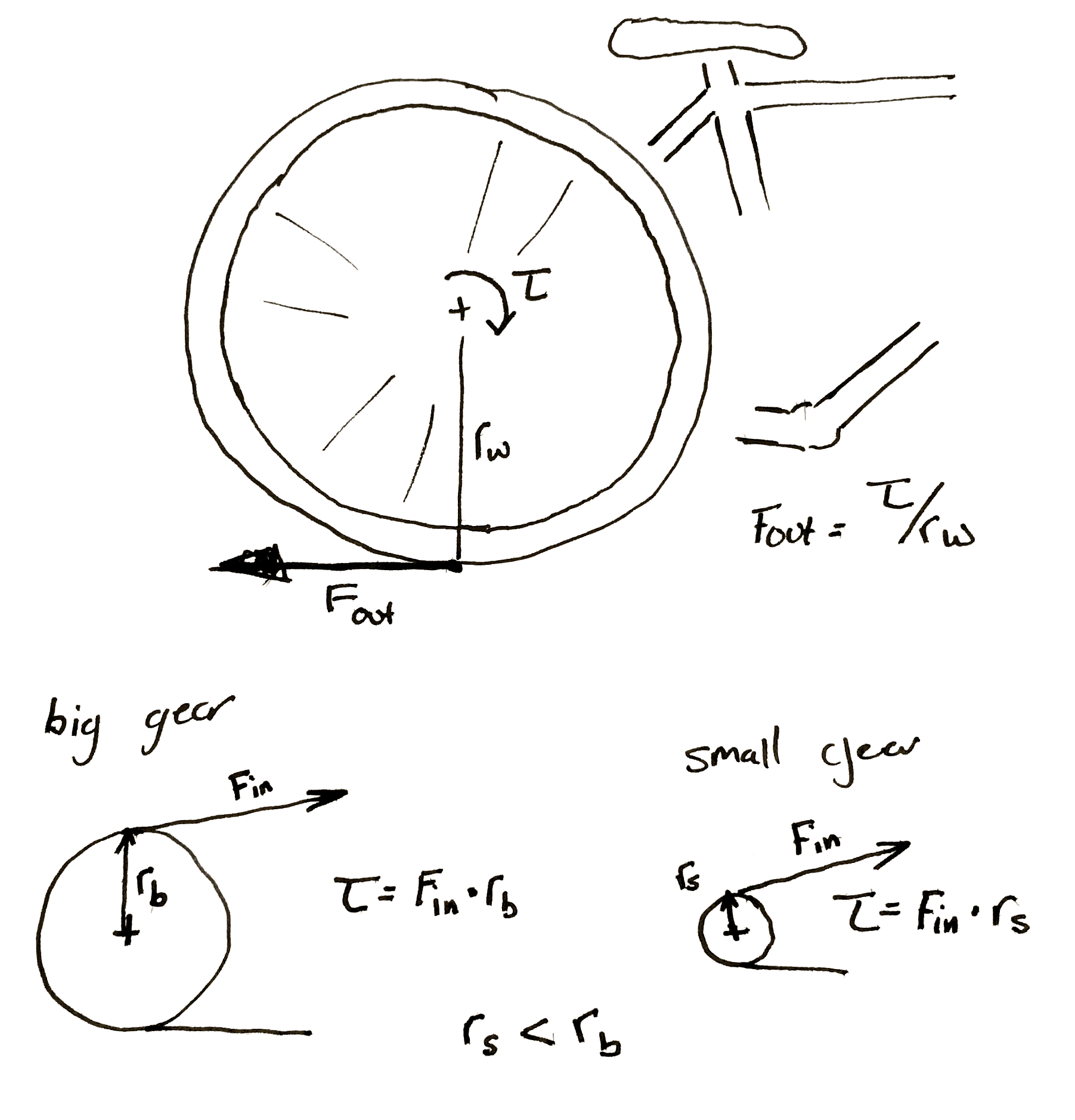
A gear is nothing more than a clever way to make two circles rotate in concert with each other as if they were perfectly joined at their circumferences. Rather than relying on the friction between two rotating disks in contact, the designer instead relies on the strength of a gear tooth as the factor limiting the amount of torque that can be applied to the gear.
Everything is in gearing is neatly proportional. As long as your point of reference is correct, and some other stuff. Uh, it gets easier with practice.
Now as my physics professors taught me to do, let’s skip the semantics and spare ourselves some pedantics. Let us assume that all gears have a constant velocity when you’ve averaged it all out. Sure there is a perceptible difference between a perfect involute and a primitive lantern gear, but for the sake of discussion it doesn’t matter at all. Especially if you’re just going to 3D print the thing. Let’s say that they’re sitting on perfect bearings and friction isn’t a thing unless we make it so. Also we’ll go ahead and make them perfectly aligned, depthed, and toleranced.
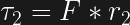
Typically, a gearbox is used for two things. You have a smaller torque that you’d like to make into a bigger one or you have one rotational velocity that you’d like to exchange for another. Typically torque is represented with a capital or lowercase Tau (Ττ) and rotational velocity likes to have a lowercase omega (ω). It also doesn’t matter at all; it just makes your equations look cooler.
Now a lot of tutorials like to start with the idea of rolling a smaller circle against a bigger one. If the smaller circle is a third as large as the big one, it will take three rotations of the small circle to make the big one rotate twice. However, it is my opinion that thinking it in terms of the force applied allows a designer to think about the gearing more effectively.
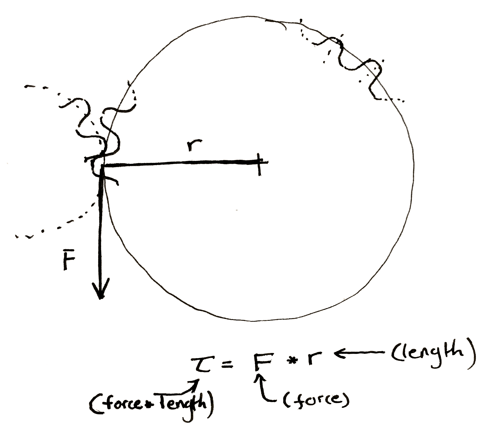
If the friction between the two surfaces of the circle is perfect, then any force applied tangentially to one of the circles will result in a perfectly perpendicular and equal force to the other circle at the point of contact between the two. Midway through writing the preceding sentence I began to understand why textbooks are so abstruse, so I also drew a picture. This results in two equations.
Now, when you have a force perpendicular to the line drawn to describe the radius, the equation for torque becomes really simple.
Multiply the length of the “lever arm”, “radius”, etc. by the force to get the preceding equations. Make sure to include the units.
You should end up force-unit * length-unit. Since I usually work in smaller gears I like to use N * mm. American websites typically use oz-in to rate motors. It is technically ozf-in (ounce-force), but the US customary system has a fetish for obtuseness.
We can make some observations. The smaller gear always sees less torque at its center. This initially seemed a bit counter-intuitive to me. If I’m using a cheater bar to turn a bolt the longer I make the bar the more torque I can put on the bolt. So if I touch the outside of a really large gear I should be seeing a ton of torque at the center of a small gear rotating along with it. However, as we mentioned before, any torque applied on the outside of the larger gear is seen equal and tangential on the smaller. It’s as if you’re touching the outside of the small gear. The torque has to be smaller.
This is why you have to pedal so much harder when the rear sprocket on a bicycle gets smaller. Each time you make the sprocket smaller you shrink the torque input into the wheel. If the perpendicular output where the wheel hits the ground is <input from the small gear> / <radius of the wheel> then it’s obvious why this happens.
Hopefully my diagram doesn’t win a prize for awfulness. Then again, an award is an award. Remember that the bicycle wheel and its input gear are rigidly attached to each other.
It’s also important to note that any time you increase the torque, the speed of the gears slow by the same proportion. If you need 60 N*m out of a motor that can give 20 N*m and you use a 3:1 gearbox to do it. If the motor previously ran at 30 rpm it’s now running at 10 rpm.
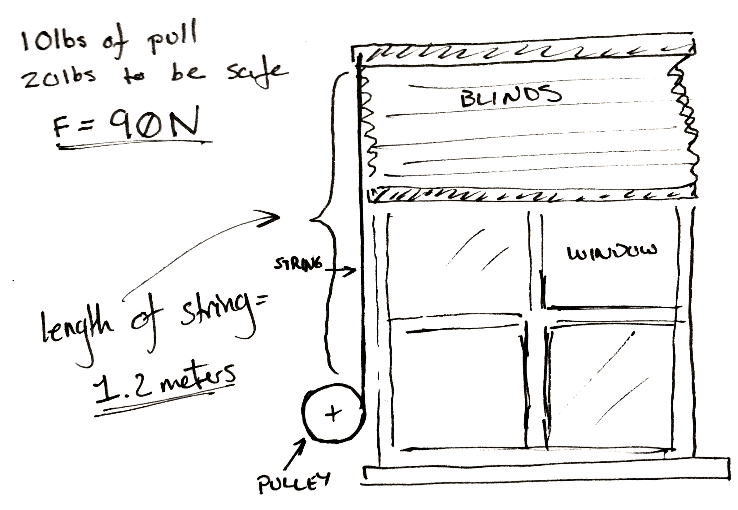
Let’s jump right into an example. Let’s say you want to make a device that automatically lifts your window blinds. You’ve got some junk and a 3D printer.
The problem set-up.
Now you’ve taken a spring scale and pulled until the shutter moves and you know you need 10 lbs. of pull to get the blinds to pull up. To make it easy on yourself you multiply this number by two so you know you need exactly 20 lbs of force to pull the curtain up. Then to make it really easy on yourself convert it all to Newtons. It’s approximately 90 N.
Now you don’t really care how fast the blinds pull up, but you go ahead and pull them up yourself. You get the feeling that the blinds won’t appreciate being lifted faster than the whole range in two seconds. You personally don’t care if takes ten seconds to, but you’d like it not to take too long.
You also measure the length of string pulled out to raise the blinds. It’s 1.2 meters.
A classic.
Lastly, you only have one spare power supply and a matching motor left in your entire laboratory after you followed the advice in a Hackaday article. Cursing the day the author was born, you sullenly write down the last specifications. You’ve got one of those cheap GM9 gear motors. 5 V, 66 rpm, and 300 N*mm. You damn him as you think fondly of your mountain of windshield washer motors and 80 lb server rack power supplies that you tossed out.
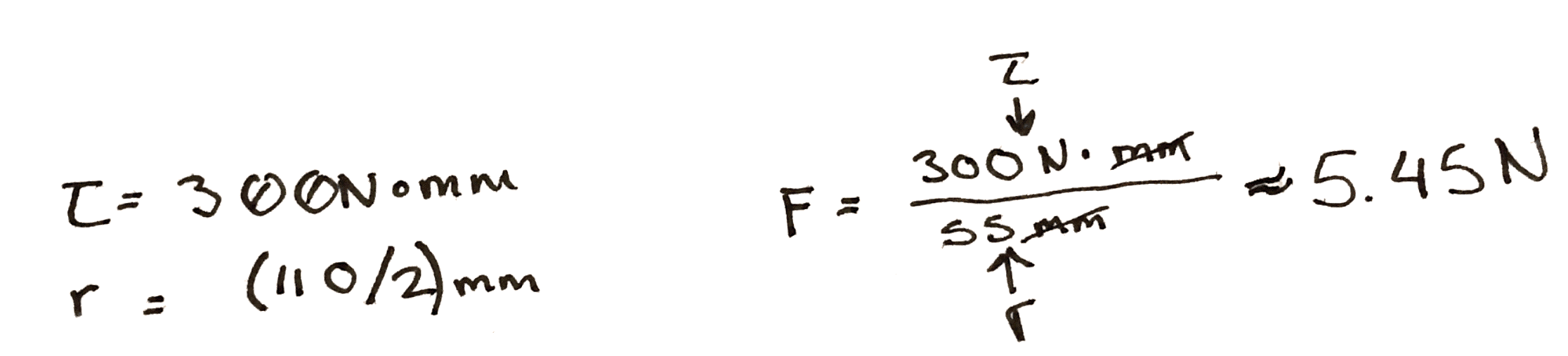
To start with, you do some experiments with a pulley. You arbitrarily pick, 3D print, and find that a 100 mm in diameter pulley seems to wind it up nicely by hand. By the end of the winding the outside diameter of the string is 110 mm. So you use the torque equations above. You find that at the end of the rotation, if you attach the motor directly, there is only 5.45 N of force being applied to the string. Not nearly enough.
Hrm..
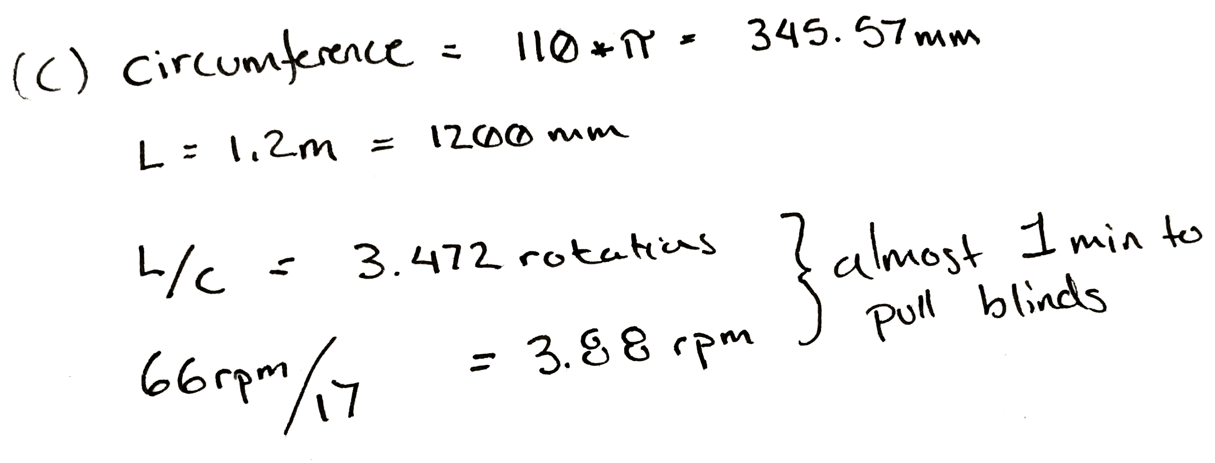
So, since you know everything is more or less proportional, you divide 90 N / 5.45 N, and arrive at an answer of 17. So, at a minimum for every turn of the pulley you need 17 turns of the motor to get the torque needed.
That would be okay, but it messes with our other specification. At a 17:1 ratio, it will take our 66 rpm motor pretty close to a minute to wind the blinds up.
Damn.
This is a moment for some pondering. Make a coffee. Maybe go write a relaxing comment to a Hackaday writer listing their various flaws, perceived and true, in excruciating detail.
What if you wound the string up on a closet rod? Those are only about 30 mm in diameter. You take a bit of rod and wind it up. It seems to work and since it’s wider the string only ends up adding 5 mm to the final diameter. You rework the calculation and find that in this case you only need a ratio of 6! Yes.
Now some of you who have done this before are likely gnashing your teeth, or more likely already down in the comments. Unfortunately it’s all proportional. While you only need a ratio of 6:1 now, nearly a third. You also need to rotate the pulley approximately three times as much to pull the same length of cord.
Sometimes you can’t win. In this case the only solution is to order a new motor. You look online for a bit and realize that one of the 12 V motors you threw away last week would work perfectly for this. You wouldn’t even need a gear box. You could attach it straight to the pulley. You look around your perfectly clean and orderly garage and feel empty.
However, just for fun you build a 6:1 gearbox anyway. It’s a hack after all.
Cover photo of the hilariously complicated Do Nothing Machine credit to the Joe Martin Foundation.
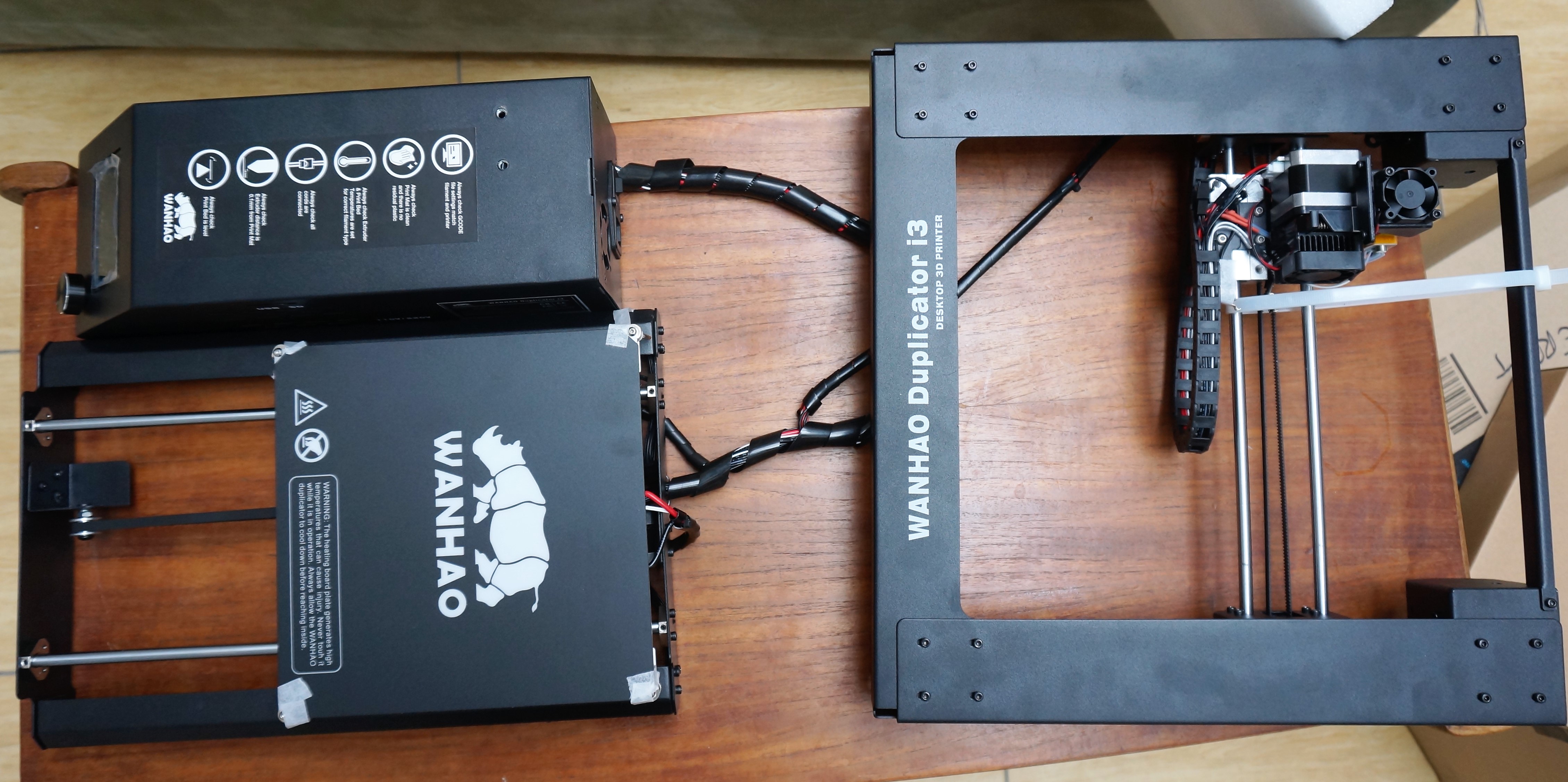
Is the Wanhao Duplicator the best printer on the market? Not at all. Is it a contender for best low-price printer?Definitely. If you consider it a low priced kit printer instead of a finished product then it’s possible that, in its price class, it is hands down the best out there.
For somewhere between 300 and 500 dollars, the Duplicator is a hell of a printer. Also selling under the name Cocoon and Maker Select, the printer is a thin folded sheet steel frame clone of the Prusa i3. I opened the box expecting the most flagrant cost cutting I could imagine. I figured the steel would be paper thin. The holes wouldn’t line up. I expected the connections to be improperly terminated. I expected a fire.
The Duplicator six screws away from being fully assembled. When the manual says find a 1m x 1m flat area to work in it’s not kidding. This table was too small.
What I got was up and printing in under an hour. What I got was something designed by someone who cares, but with an obvious cost goal. As a bonus, it even printed pretty well. As mentioned, the basic shape of the frame is that of a Prusa i3. A horizontal bit holds the bed and y movement. A vertical bit is attached to the middle of that, making a T. It holds the X, Z, and nozzle.
 Well, maybe not, but [Mariko Kosaka]’s father [Kimio Kosaka] has done it. In order to build the matrix, he needed tools that could reach inside the mouth of the bottle without taking up too much space to allow for precise movement. To do this he bent, brazed, twisted, and filed piano wire into tools that are quite beautiful by themselves. These were used to carefully bend and position the LEDs, wires, and other components inside the bottle.


 It’s all based around a simple board. An encapsulated power supply converts the 220V offered by the Bulgarian power authorities into two rails of 3.3V and 5V respectively. The 3.3V is used for an ESP8266 whose primary concern is the control of a triac and an RGB LED. The 5V is optional if the user decides to add a shield that needs it. That’s right, your light switches will now have their own shields that decide the complexity of the device.