Auto-Aiming Nerf Gun To Give You The Edge In Battle

Ever wished for some robotic enhancements for your next nerf war? Well, it’s time to dig through the parts bin and build yourself a nerf gun with aimbot built right in, courtesy of [3Dprintedlife]. (Video, embedded below.)

The gun started with a design borrowed from [Captain Slug]’s awesome catalog of open source nerf guns. [3Dprintedlife] modified the design to include a two-axis gimbal between the lower and the upper, driven by a pair of stepper motors via an Arduino. For auto-aim, a camera module attached to a Raspberry Pi running OpenCV was added. When the user half-pressed the trigger, OpenCV will start tracking whatever was at the center of the frame and actively adjust the gimbal to keep the gun aimed at the object until the user fires. The trigger mechanism consists of a pair of microswitches that activate a servo to release the sear. It is also capable of tracking a moving target or any face that comes into view.

We think this is a really fun project, with a lot of things that can be learned in the process. Mount it on a remote control tank and you’d be able to wage some intense battles in your backyard. All the files are available on GitHub.

You are never too old for a good old nerf battle. Whether you want to be a sniper, a machine gunner, or a heavy weapons specialist, there’s a weapon to build for every role.

Tiny PCB Motor Robot Is Making Its First Wobbly Moves

[Carl Bugeja] has been working on his PCB motors for more than three years now, and it doesn’t seem like he is close to running out of ideas for the project. His latest creation is a tiny Bluetooth-controlled robot built around two of these motors.

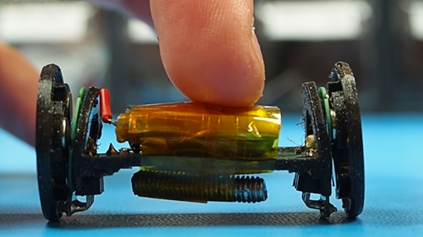
One of the main challenges of these axial flux PCB motors is their low torque output, so [Carl] had to make the robot as light as possible. The main board contains a microcontroller module with integrated Bluetooth, an IMU, regulator, and two motor drivers. The motor stator boards are soldered to the main board using 90° header pins. The frame for the body and the rotors for the motors are 3D printed. A set of four neodymium magnets and a bearing is press-fit into each rotor. The motor shafts are off-the-shelf PCB pins with one end soldered to the stator board. Power comes from a small single-cell lipo battery attached to the main board.

The robot moves, but with a jerking motion, and keeps making unintended turns. The primary cause of this seems to be the wobbly rotors, which mean that the output torque fluctuates throughout the rotation of the motor. Since there are only two points of contact to the ground, only the weight of the board and battery is preventing the central part from rotating with the motors. This doesn’t look like it’s quite enough, so [Carl] wants to experiment with using the IMU to smooth out the motion. For the next version, he’s also working on a new shaft mount, a metal rotor, and a more efficient motor design.

We look forward to seeing this in action, and also what other application [Carl] can come up with. He has already experimented with turning it into a stepper motor, a linear motor, and a tiny jigsaw motor.

Continue reading “Tiny PCB Motor Robot Is Making Its First Wobbly Moves”

Robot Moves In Any Direction On Ball Wheels

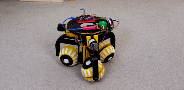
The ability to move in any direction and turn on the spot is a helpful feature on robots that operate indoors around other objects. [James Bruton] demonstrated one possible solution in the form of a robot chassis that can move in any direction with three ball-shaped wheels.

The video after the break is part two of this series. Part one covered the ball wheels themselves, consisting of a pair of half-spheres that can rotate independently with a small roller in the center of each and a driven shaft through the center of the sphere. Three of these are arranged at 120° intervals around the center of the robot, with the main shafts driven by geared DC motors using belts. To move in a straight line some basic trigonometry is used to calculate the required relative speed of each wheel. An Arduino Mega is used to do the necessary calculation when receiving input from the wireless controller.

The motion is remarkably smooth, and we’d be interested to see how it compares with Mecanum and Omniwheels. It seems like the perfect platform for [James]’ Really Useful Robot. He hinted that he might mount a trash bin on it in the future. We would love to see an automatic trash-catching robot, similar to [StuffMadeHere]’s robotic basketball hoop. Continue reading “Robot Moves In Any Direction On Ball Wheels”

3D Printed Flip Dots

Displays have come a long way in the last few decades, but none can deliver the mesmerizing visual and audio experience of a large flip dot display. Both old panels and new panels can be expensive and difficult to source, so [Larry Builds] made his own flip dots with the help of 3D printing.

Flip dots are driven by a pair of electromagnetic posts that attract or repel a magnet embedded in the dot, and [Larry Builds] version is no different. For the electromagnets, he used M3 threaded rod with enamel wire wound around them using a drill. At first, he used a large magnet in the center of the 3D printed dot, but the magnetic field was large and strong enough to flip the surrounding dots in an array. He then changed the design to a small 4 mm diameter magnet in the edge that aligns directly with the electromagnets. This design looks very similar to those used by Breakfast for their massive installations. By modifying electromagnets and adding spacers around the magnets, he was able to reduce the operating current from 2 A to below 500 mA. [Larry Builds] also breadboarded a basic driver circuit consisting of H-bridges multiplexed to rows and columns with diodes.

We will be keeping a close eye on this project, and we look forward to seeing it evolve further. It’s definitely on our “things to build” list. We’ve embedded multiple videos after the break showing the progress thus far.

We’ve covered several interesting flip dot projects, including a water level indicator that doesn’t use any electronics and another that is crocheted. Continue reading “3D Printed Flip Dots”

Investigating A New Chip In A Minimalist LED Lamp

Teardowns of cheap electronic devices can produce results that are interesting, horrifying, or both, especially when mains power is involved. [bigclivedotcom] gave a minimalist LED lamp his reverse engineering treatment, and discovered a new chip that requires only four additional passive components to run LEDs on AC power.

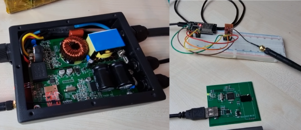
The chip in question is a Joulewatt JWB1981, for which no datasheet is available on the internet. However, there is a datasheet for the JW1981, which is a linear LED driver. After reverse-engineering the PCB, [bigclivedotcom] concluded that the JWB1981 must include an onboard bridge rectifier. The only other components on the board are three resistors, a capacitor, and LEDs. The first resistor limits the inrush current to the large smoothing capacitor. The second resistor is to discharge the capacitor, while the final resistor sets the current output of the regulator. 

It is possible to eliminate the smoothing capacitor and discharge resistor, as other LED circuits have done, which also allow the light to be dimmable. However, this results in a very annoying flicker of the LEDs at the AC frequency, especially at low brightness settings.

As always, this is a very informative video from [bigclivedotcom], and it was all done based on a single picture of the PCB sent in by a viewer. He also mentions that the lifespan of the lamp would likely be increased by swapping out the current setting resistor for a larger one.

We’ve covered several [bigclivedotcom]’s videos, covering topics from self-powered wireless switches to filling up fake capacitors with electrolyte.

Continue reading “Investigating A New Chip In A Minimalist LED Lamp”

WiFi Penetration Testing With An ESP32

WiFi is one of those technologies that most of us would have trouble living without. Unfortunately, there are several vulnerabilities in the underlying 802.11 standards that could potentially be exploited. To demonstrate just how simple this can be, [risinek] developed the ESP32 Wi-Fi Penetration Tool that runs on cheap dev boards and can execute deauthentication and Denial of Service attacks, and capture handshakes and PMKIDs.

The main challenge in this project is to implement these attacks while using the ESP-IDF development framework. The closed source WiFi libraries of the ESP-IDF block specific arbitrary frames like deauthentication frames. To get around this [risinek] used two different approaches. The first is to bypass the declaration of the blocking function at compile-time, which is borrowed from the esp32-deauther project. The second approach doesn’t require any modifications to the ESP-IDF. It works by creating a rogue access point (AP) identical to the targeted access point, which will send a deauthentication frame whenever one of the devices tries to connect to it instead of the real AP.

WPA/WPA2 handshakes are captured by passively listening for devices connecting to the target network, or running a deauth attack and then listening for when devices reconnect. PMKIDs are captured from APs with the roaming feature enabled, by analyzing the first message of a WPA handshake. ESP32 Wi-Fi Penetration Tool will also format the captured data into PCAP and HCCAPX files ready to be used with Wireshark and Hashcat. To manage the tool, it creates a management access point where the target and attack type is selected, and the resulting data can be downloaded. Pair the ESP32 with a battery, and everything can be done on the go. The project is part of [risinek]’s master’s thesis, and the full academic article is an educating read. Continue reading “WiFi Penetration Testing With An ESP32”

All-Wheel Drive Bicycle Using Hand Drill Parts

A skilled mountain biker can cross some extreme terrain, but [The Q] thought there might be room for improvement, so he converted a fat bike to all-wheel drive.

The major challenge here is transferring pedal power to the front wheels, especially around the headset. [The Q] solved this by effectively building a differential from the parts of a very old hand drill. Since the front wheel needs to rotate at the same speed as the rear, one long chain loops from the rear wheel to the headset, tensioned by a pair of derailleurs. This front sprocket turns a series of spur gears and bevel gear arranged around the headset, which transfers the power down to the front wheel via another chain.

It would be interesting to feel what the bike rides like in soft sand, mud, and over rocks. We can see it has some advantages in those conditions but were unsure if it would be enough to offset the penalty in weight and complexity. The additional chains and gears certainly look like they’re asking to catch foliage, clothing, and maybe even skin. However, we suspect [The Q] was more likely doing it for the challenge of the build, which we can certainly appreciate. With the rise of e-bikes, adding a hub motor to the front wheel seems like a simpler option.

We’ve seen several interesting bicycle hacks over the years, including a strandbeest rear end, 3D printed tires and an automatic shifter. Continue reading “All-Wheel Drive Bicycle Using Hand Drill Parts”