Screwy Math For Super Fine Adjustments: Differential Screws

For any sort of precision machine, precision adjustability is required. For the hacker this usually involves an adjustment screw, where the accuracy is determined by the thread pitch. This was not good enough for [Mark Rehorst] who wanted adjustment down to 10 μm for his 3D printer’s optical end-stop, so he made himself a differential adjustment screw.

Tiny adjustment can be made to the green block due to the thread pitch differences

Differential screws work by having two threads with a slightly different pitch on the same shaft. A nut on each section of thread is prevented from rotating in relation to the other, and when the screw is turned their relative position will change only as much as the difference between the two thread pitches.

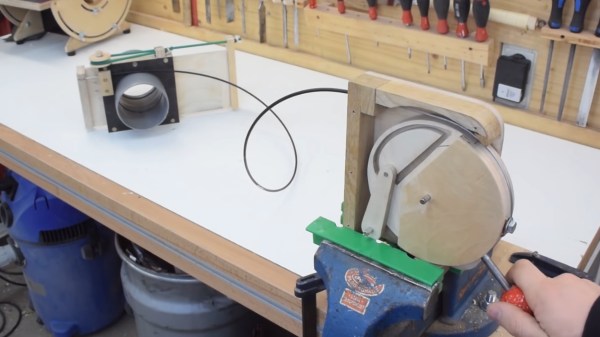
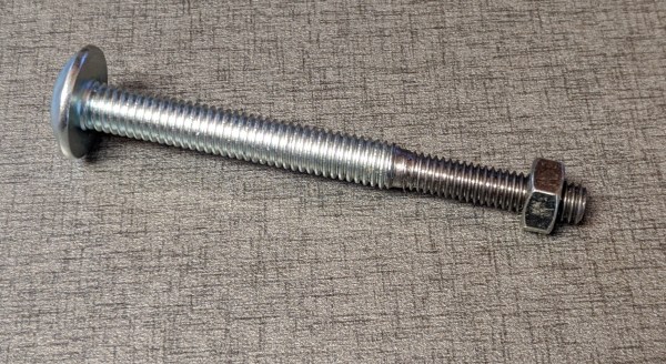
The differential screw in this case started life as a normal M5 bolt with a 0.8 mm thread pitch. [Mark] machined and threaded section of the bolt down to a M4 x 0.7 mm thread. This means he can get 0.1 mm (100 μm) of adjustment per full rotation. By turning the bolt 1/10 rotation, the  relative movement comes down to 10 μm.

This mechanism is not new, originating from at least 1817. If you need fine adjustments on a budget, it’s a very elegant way to achieve it and you don’t even need a lathe to make your own. You can partially drill and tap a coupling nut, or make a 3D printed adapter to connect two bolts.

Fabricating precision tools on a budget is challenging but not impossible. We’ve seen some interesting graphite air bearings, as well as a 3D printed microscope with a precision adjustable stage.

Pop A Wheelie With Your Electric Skateboard, The Hacker Way

Using a bit of tech to make up for a lack of skill is a time-honoured tradition, otherwise known as cheating among those who acquired the skill the hard way. Learning to wheelie manual a skateboard is usually paid for in bruises, but [blezalex] got around that by letting his electric skateboard handle the balancing act.

At first glance the board looks and rides like an average DIY electric skateboard, with an off-the-shelf  a dual hub motor truck, VESC speed controllers and a wireless throttle. The party trick appears when the front wheel is popped off the ground, which activates the secret self-balancing mode. At this point a STM32F401 dev board and MPU-6050 IMU take over control of the motors, which is in turn controlled by leaning forward or backwards, like a hoverboard. The remote throttle turns into a dead man switch, which cuts power to the motors when released.

[blezalex] says he has had less that an hour of skateboard time in his life before getting on this one, which is a good testament of just how well it works. The biggest challenge was in getting the board to turn while on two wheels, which was solved by sensing side-to-side tilt of the board with the IMU and applying proportional differential torque to the wheels. With a bit of practice it’s also possible to smoothly shift between riding modes while moving.

We think this is a really elegant cheat, now we need to build one of our own. Fortunately the STM32 firmware and instructions are all up on GitHub. Building your own electric skateboard has become really simple with the availability of off-the-shelf components. We’ve also seen a bicycle with a wheelie cheat device to prevent you falling on your back

Silo Launched Model Rocket Goes Thoomp

While rockets launched from silos are generally weapons of war, [Joe Barnard] of [BPS.Space] thought model rocketry could still do with a little more thoomp. So he built a functional tube launched model rocket.

Like [Joe]’s other rockets, it features a servo-actuated thrust vectoring system instead of fins for stabilization. The launcher consists of a 98 mm cardboard tube, with a pneumatic piston inside to eject the rocket out of the tube before it ignites its engine in mid-air. When everything works right, the rocket can be seen hanging motionlessly in the air for a split second before the motor kicks in.

The launcher also features a servo controlled hatch, which opens before the rocket is ejected and then closes as soon as the rocket is clear to protect the tube. The rocket itself is recovered using a parachute, and for giggles he added a tiny Tesla Roadster with its own parachute.

Projects as complex as this rarely work on the first attempt, and Thoomp was no exception. Getting the Signal flight computer to ignite the rocket motors at the correct instant proved challenging, and required some tuning on how the accelerometer inputs were used to recognize a launch event. The flight computer is also a very capable data logger, so every launch attempt, failed or successful, became a learning opportunity. Check out the second video after the break for a fascinating look at how all this data was analyzed.

[Joe]’s willingness to fail quickly and repeatedly as part of the learning process is a true display of the hacker spirit. We’ll definitely be keeping a close eye on his work.

Continue reading “Silo Launched Model Rocket Goes Thoomp

Rover Runs Slow And Steady On Solar Power

The solar panel technology we have available today doesn’t really lend itself to practical everyday transport. But when speed isn’t a concern, it can make for some very interesting autonomous rovers. One example of this is [Daniel Riley] aka [rctestflight]’s solar powered rover, which he built to live autonomously at his flight testing field, crawling around whenever it has gathered enough juice from the sun.

[Daniel] has thing for autonomous craft of all types, with quite a few aircraft and boats to his name. This rover is built around a welded steel frame, with each wheel driven by a brushless geared motors via a chain. While it’s technically a skid steer, the electronic speed controls are from a quadcopter and can’t reverse, so it doesn’t turn quite on the spot.

With the rigid steel frame, any small bump in the ground would cause one wheel to lose traction. To fix this, the frame was cut in two and a pivot added in the center, allowing all four wheels to always remain on the ground. Another problem is that the wheels would sometimes dig themselves into the soft wet ground, so this, [Daniel] attached a 3D printed “hump” to each drive wheel, which helps them to climb out of any soft spots. For the next version of this rover, [Daniel] plans to use cheap DC geared motors from a Barbie jeep. They’re a bit too fast though, so he’ll be adding 3D printed cycloidal reduction gearboxes. We’re definitely looking forward to seeing here this project goes from here.

There have been a number of projects to test solar powered robots for agricultural use. We really like the idea, with its potential for long duration missions. Imagine something like this roaming the Black Rock playa in the US, the Makgadikgadi Pan in Botswana, or even the Sahara Desert, while gathering environmental data and making awesome time-lapse videos.

Gripper Uses Belts To Pinch And Grasp

For all the work done since the dawn of robotics, there is still no match for the human hand in terms of its dexterity and adaptability. Researchers of the IRIM Lab at Koreatech is a step closer with their ingenious BLT gripper, which can pinch with precision or grasp a larger object with evenly distributed force. (Video embedded below.)

The three fingered gripper is technically called a “belt and link actuated transformable adaptive gripper with active transition capability”. Each finger is a interesting combination of a rigid “fingertip” and actuation link, and a belt as a grasping surface. The actuation link has a small gearbox at it’s base to open and close the hand, and the hinge with the “fingertip” is spring-loaded to the open position. A flexible belt stretches between the finger tip and the base of the gripper, which can be tensioned to actuate the fingertip for pinching, or provide even force across the inside of the gripper for grasping. Two of the fingers can also rotate at the base to give various gripper configurations. This allows the gripper to be used in various ways, including smoothly shifting between pinching and grasping without dropping a object.

We love the relative simplicity of the mechanism, and can see it being used for general robotics and prosthetic hands, especially if force sensing is integrated.  The mechanism should be fairly easy to replicate using 3D printed components, a piece of toothed belt, and two cheap servos, so get cracking! Continue reading “Gripper Uses Belts To Pinch And Grasp”

Sonic The Self-Balancing Robot: Face-Plants And The Challenges Of Sensor Integration

Watching a child learn to run is a joyous, but sometimes painful experience. It seems the same is true for [James Bruton]’s impressive Sonic the Self-Balancing robot, even with bendable knees and force sensitive legs.

We covered the mechanical side of the project recently, and now [James] has added the electronics to turn it into a truly impressive working robot (videos after the break). Getting it to this point was not without challenges, but fortunately he is sharing the experience with us, wipe-outs and all. The knees of this robot are actuated using a pair of motors with ball screws, which are not back drivable. This means that external sensors are needed to allow the motors to actively respond to inputs, which in this case are load cells in the legs and an MPU6050 IMU for balancing. The main control board is a Teensy 3.6, with an NRF24 module providing remote control.

[James] wanted the robot to be able to lean into turns and handle uneven surfaces (small ramps) without tipping or falling over. The leaning part was fairly simple (for him), but the sensor integration for uneven surfaces turned out to be a real challenge, and required multiple iterations to get working. The first approach was to move the robot in the direction of the tipping motion to absorb it, and then return to level. However, this could cause it to tip over slightly larger ramps. When trying to keep the robot level while going over a ramp with one leg, it would go into wild side-to-side oscillations as it drops back to level ground. This was corrected by using the load cells to dampen the motion.

Continue reading “Sonic The Self-Balancing Robot: Face-Plants And The Challenges Of Sensor Integration”

Cable Operated Blast Door Needs No Power

Every well-equipped wood shop has a dust collection system, with blast gates at every tool to direct the suction power where you need it. If these gates are hard to reach they can be real pain to operate. [Cosmas Bauer] had this problem with his table saw, and created a convenient cable-operated mechanism.

The dust chute on table saw is on the back end, meaning he needs to walk around it to open it, and then walk back to the front to operate the machine. As we all know, laziness increased efficiency can be an excellent reason for projects. Electronics or pneumatics might get the job done, but [Cosmas] realised that a mechanical system might be simpler and more reliable.  Being a woodworker, he built most of the system out of wood.

The blast door itself is held in the closed position by a piece of elastic tubing. To pull it open, he attached a bicycle cable to the blast door, with the other side attached to a latching mechanism that is the star of the show. It’s a rotating disc, with the end of the cable and operating handle attached on the outer edge. A slot track is cut in the disc, in which a pin on the end of a short arm slides. It has a few sharp corners in the track, which forces the pin to only go around in one direction, and to latch in two possible positions when released. Check out the video after the break to see it in action.

Continue reading “Cable Operated Blast Door Needs No Power”