Bubbly Filament Works Better Than You Think

Normally bubbles appearing in your extruded filament would be considered a bad sign, but it turns out you can now buy filament that has been specifically formulated to foam. [Stefan] from CNC Kitchen has doing some experiments with these bubbly filaments, and the results have been very interesting.

The filaments in question are VARIOSHORE TPU and LW-PLA, both by ColorFabb. Both filaments have a blowing agent added to the formulation, which releases gas as the temperature is increased. This causes bubbles to form, creating a cellular structure, which decreases the density and increases the flexibility of the printed part. This isn’t the first time that foaming is sold as a feature, but previously it was only done for aesthetic purposes in Polymaker’s Polywood filament.

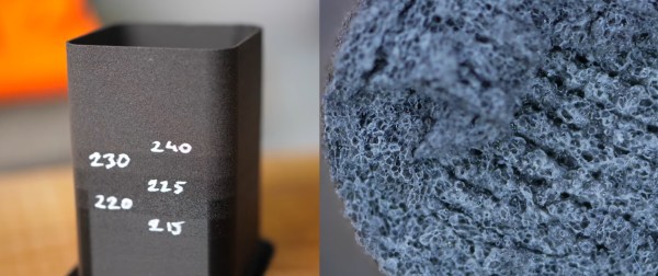
Before putting the materials through his excellent test procedures, [Stefan] first goes through the process of tuning the print settings. This can be tricky because of the foaming, which increases the effective volume of the plastic, requiring careful adjustment of the extrusion rate. Foaming in the PLA filament reached its maximum foaming at 250 C, at which its density was 44% of the unfoamed filament.

In testing the physical properties, [Stefan] found that the tensile strength and stiffness of printed parts are reduced as foaming increases, but the impact strength is improved. He concludes that the lightweight PLA can have some interesting applications because of the reduced weight and increased impact strength, with 3D printed RC aircraft being an excellent example of this. It should also be possible to change the between layers, effectively sandwiching the foamed layers between solid skins.

[Stefan]’s videos are an excellent resource for those looking to master the finer points of 3D printing with different materials. He has reinforced prints with carbon fiber, played with extrusion widths and developed an ingenious gradient infill technique.

Continue reading “Bubbly Filament Works Better Than You Think”

Wall Panels With 3760 Antennas Can Increase Wireless Range

Most of us know that to get the best possible WiFi signal, you want there to be as few walls as possible between you and the Access Point. But that might soon change, as researchers at MIT have found a way to make surfaces increase signal strength. Called RFocus, the technique uses a wall panel covered in simple antennas to dynamically focus or reflect RF energy towards a intended receiver.

The normal methods to increase wireless range usually involve increasing the transmitter output or adding larger, more efficient, or directional antennas to the receivers and transmitters. But these techniques are limited when you need to the reduce power consumption and size of the devices. The MIT teams approached the problem from a completely different angle, by optimizing the environment.

The wall panel in question consist of 94 PCBs, each containing 40 passive antenna elements in the form of copper rectangles. Each element is a quarter wavelength long (125 mm for 2.4 Ghz), and on its own it doesn’t have any real effect on the signals, allowing it to pass through the panel. Between the ends of elements are small RF switches, that can close to combine two antenna elements into single half wavelength antenna, creating a reflector. When this is applied across the panel in different patterns it can effectively beamform the signal to focus it at different points in space.

The RF switches are connected to shift registers, which are all controlled via a single SPI bus with an Arduino. Each RF switch is activated in a pseudo-random sequence, changing the configuration of the panel 10,000 times in 100 ms. The signal strength at the receiver is reported to the panel controller for each configuration, allowing the controller to select the best configuration for any single transmitter. In a scenario where multiple low-power sensor nodes are deployed, this can allow the receiver to “focus” on each node in turn. The full paper is a very interesting read, downloadable as a PDF.

RF is generally considered the black magic of electronics, but it can all become a bit clearer with a basic knowledge of antenna theory and modulation schemes.

Thanks to [Qes] for the tip!

Simple 3D Printed Robotic Arm Uses Compliant Mechanism

Learning through play is effective for humans of all ages, and since 2016 [slantconcepts] has been designing STEM kits that help teach kids to build their future overlords. They are launching version 3 of their LittleArm robotic arm, and the progression from version 1 is an interesting study in simplification and parts count reduction without sacrificing functionality.

In all of the LittleArm versions the main mechanical components are 3D printed, and driven by 3 servos for motion plus one additional servo to run the gripper. These kits are specifically intended to be built and disassembled repeatedly, and classrooms are a great place for small screws to easily disappear, so reducing the number of screws was a big goal for v3. The gripper/forearm shows the most dramatic improvement from the previous versions, being simplified from 8 separate components to a single 3D printed part by using a compliant mechanism — that squiggly pattern that allows the gripper to flex into place. The gripper tips also feature a simple “cutout” that allow it more easily grasp horizontal objects.

An Arduino Nano based expansion board is used to control the arm, with a HC-06 Bluetooth module to allow it to be controlled via a smart phone app. Various sensors can also be added to expand the kit’s capabilities. Unfortunately the mechanical design is not open source, but it can still be a source of inspiration for your own design projects.

Hopefully this kit will inspire some future hackers to build a more advanced 3D printed version, or even a giant hydraulic powered arm.

Automatic Component Tape Cutter For When Your Electronics Kit Hits The Big Time

Even for the simplest of products, production at scale can be big challenge. For example, you might find yourself spending many hours manually counting and cutting strips of component tape to go with the DIY electronics kit your selling on Tindie. [Tom Keddie] found himself in similar position some time ago, and built himself an automated component counter and tape cutter.

[Tom] posted the video of his old machine (see it after the break) after a call for help from another Twitter user who found himself with a lot of component strips to cut. The frame of the machine is made from 20×20 aluminium extrusions and laser cut plexiglass. The tape is pulled off the reel by a stepper motor using a 3D printed sprocket, with the tape held on by Lego wheel and tension spring. A second idler sprocket with tensioner is used to guide the tape through two photo-interrupters that can count holes in opaque tape or the components in clear tape. The cutter itself it an Exacto blade mounted on a wooden block in a guillotine-like arrangement, driven by another stepper motor and a threaded rod as lead screw. Everything is of course controlled by an Arduino. Although not used any more, [Tom] says it worked very well in its day.

The availability of cheap laser cutting, 3D printing and components like aluminium extrusions and stepper motors have really made it possible for anyone to add some automation to production in the home workshop. You won’t be surprised that we’ve seen something like this before, but we’ve also seen similar machines for wiring prep and through-hole resistors. Let us hear your production hacks in the comments, or drop us a tip if you’ve documented it!

Continue reading “Automatic Component Tape Cutter For When Your Electronics Kit Hits The Big Time”

Sonic The Hedgehog Self-Balancing Robot Can Bend At The Knees

Building your own self-balancing robot is a rite of passage for anyone getting into the field of robotics. Master of robots, [James Bruton] has been there, done that, and collected a few T-shirts. Now he’s building a large Sonic the Hedgehog self balancing robot that can bend at the knees and hip, allowing it to lean while turning and handle uneven terrain. Check out the first video embedded after the break.

Standing about 1 m tall, the robot is inspired by Boston Dynamic’s box handling bot, Handle. It’s “skeleton” consists of 20×20 aluminium extrusions, bolted together using a bunch of 3D printed fittings in the signature blue and red of Sonic. The wheels and tyres are also 3D printed, and driven by brushless motor via a toothed belt. The knee/hip mechanism is actuated using a ball screw, also driven by a brushless motor.

[James] intends to implement an active shock absorption system into the leg mechanism, using the same technique he tried on his OpenDog robot. It works by bolting a load cell onto one of the leg extrusion to sense when it flexes under load, and then actuating the knee mechanism to absorb the force. His first version of the system on OpenDog used PWM signals to send the load cell data to the main controller, but the motors on the legs induced enough noise in the signal wires to make it unusable. He has since started experimenting with the CAN bus protocol, which was specifically designed to work reliably in noisy systems like modern automobiles. If he gets it working on the two legs of this Sonic robot, he plans to also implement it on the quadruped OpenDog.

Continue reading “Sonic The Hedgehog Self-Balancing Robot Can Bend At The Knees”

SMA-Q2 Smart Watch Is Completely Hackable

The search for the ultimate hacker’s smart watch probably won’t end any time soon. [emeryth] has nominated another possible candidate in the form of the SMA-Q2, and has made a lot of progress in making it accessible.

Also known as the SMA-TIME, the watch is based around the popular NRF52832 Bluetooth SoC, with a colour memory LCD, accelerometer, and a heart rate sensor on the back. The main feature that makes it so easy to hack is the stock bootloader on the NRF52832 that works with generic Nordic upload tool, making firmware upgrades a breeze via a smart phone. Unfortunately the bootloader itself is locked, so it must be completely wiped to gain debugging access. The hardware configuration has also been well reverse engineered with all the details available.

Custom main board with a NRF52840 module

[emeryth] has most of the basic features working with his custom firmware, although it’s still in the early stages. He designed a new watch face that includes weather updates and basic audio controls. The 3-bit display’s power consumption has also been reduced by only refreshing the necessary parts. The heart rate sensor outputs the raw waveforms, and it’s pretty accurate after a bit of FFT and filtering magic. Built-in tap and tilt detection is available on the accelerometer, which works well, but strangely doesn’t appear to have been used in the stock firmware.

Unfortunately the original enclosure design that used screws was dropped for glued version. It’s still possible to open without breaking anything, just a bit more difficult. [emeryth] Another hardware hacker named [BigCorvus] has even designed a completely new open-source main board with a NRF52840 module and heart rate sensor on a small flex PCB, with everything up on GitHub.

We really hope the community takes a liking to this watch, and look forward to seeing some awesome hacking. This is an excellent addition to the list of candidates for the perfect hacker’s smart watch that [Lewin Day] has already investigated . We also see a lot of DIY smart watches including one with a beautiful wood-filled 3D printed housing and another with LED matrix display.

RF Modulation: Crash Course For Hackers

When you’re looking to add some wireless functionality to a project, there are no shortage of options. You really don’t need to know much of the technical details to make use of the more well-documented modules, especially if you just need to get something working quickly. On the other hand, maybe you’ve gotten to the point where you want to know how these things actually work, or maybe you’re curious about that cheap RF module on AliExpress. Especially in the frequency bands below 1 GHz, you might find yourself interfacing with a module at really low level, where you might be tuning modulation parameters. The following overview should give you enough of an understanding about the basics of RF modulation to select the appropriate hardware for your next project.

Three of the most common digital modulation schemes you’ll see in specifications are Frequency Shift Keying (FSK), Amplitude Shift Keying (ASK), and LoRa (Long Range). To wrap my mechanically inclined brain around some concepts, I found that thinking of RF modulation in terms of pitches produced by a musical instrument made it more intuitive.

And lots of pretty graphs don’t hurt either. Signals from two different RF dev boards were captured and turned into waterfall and FFT plots using a $20 RTL-SDR dongle. Although not needed for wireless experimentation, the RTL-SDR is an extremely handy debugging tool, even to just check if a module is actually transmitting. Continue reading “RF Modulation: Crash Course For Hackers”