
Writing an operating system for a computing platform is one of those non-trivial tasks few people actually need to do, regardless of whether it’s for a small microcontroller or a larger general-purpose computer. Many of us spend a large amount of our time working on producing robust code for embedded systems, occasionally diving deeper into the abstraction when we’re stuck on a problem. Quite often this work is sitting on top of an RTOS, which we consider a solved problem. [Jonathan Diamond] had picked up a fair bit of knowledge of some of the low-level AVR black magic, as well as some details of how operating systems work internally, and so decided to have a crack a building a toy operating system called KittyOS, for the learning experience alone.
[Jonathan] hastens to add that this is not a practical OS, but a learning platform that needs a few more bells and whistles added to be useful. Aimed at the 8-bit AVR ATmega168 with its mere 16kB of flash and 1kB of SRAM, the diminutive chip can still perform more than well enough to host the rudimentary OS — up to four application tasks, and some basic system call support.
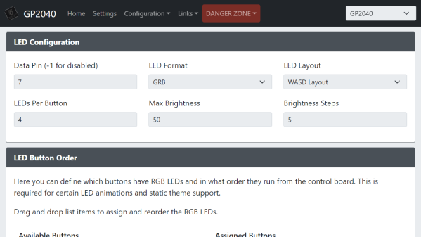
Already, KittyOS sports preemptive multitasking, with prioritization and support for applications written in C. Hardware support is a bit limited, with just serial I/O and a spot of GPIO, but that’s more than enough for a demonstrator. Applications can be loaded into any of the four available slots, with per-slot run state control, using the Python-based host interface. The post is a long one, with an absolute ton of the gory details we love around these parts, and we’re very glad [Jonathan] took the time to make a proper write-up as well as a demonstration video, which can be found after the break.
Continue reading “KittyOS: Writing A Toy OS For The ATmega168 From Scratch”


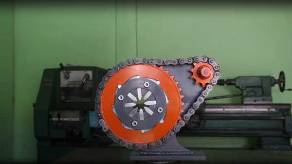
 crimping profile. A small piece of steel was welded on to each, to allow a small spring to act on the finger, enabling it to retract at the end of the crimping action. We did spot the steel plate being held in place with a small magnet, prior to welding. The heat from that would likely kill off the magnetic field in a short space of time, but they’re so cheap as to be disposable items anyway.
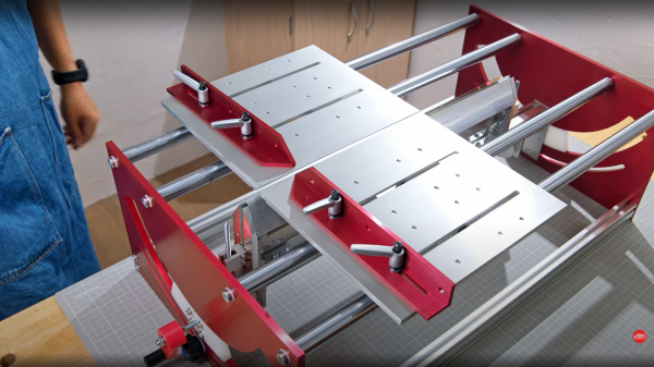
 which might be a bit tricky to track down if you were so inclined to reproduce the build. It appears (well if you believe the auto-translation by Google Lens, anyway) to be a spare blade for a commercial guide saw available in Japan at least.