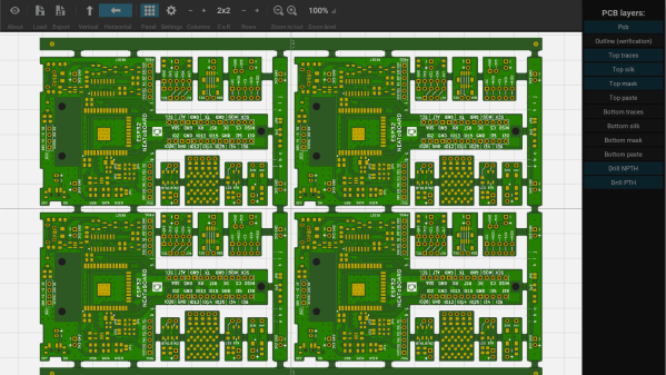
When you’re working with PCBs and making single units to knock out in those Chinese fabs, going from layout to manufacturable Gerber files is just a few button presses, no matter what PCB layout tool you prefer. But, once you get into producing sets of PCBs that form a larger system, or are making multiple copies for efficient manufacturing, then you’re not going to get far without delving into the art of PCB panelization. We’ve seen a few options over the years, and here’s yet another one that’s looking quite promising — hm-panelizer by [halfmarble] is a cross platform Python GUI application, which leverages Kivy, so it should run on pretty well on most major platforms without too much hassle. The tool is early in development, so is restricted to handling only straight PCB edges, with horizontal mouse-bites for now, but we’re sure it will quickly grow more general purpose capabilities given time and support.
In an ideal world, open source tools like KiCAD would have a built-in panelizer, but for now we can dream and hm-panelizer might just be good enough for some people. For more choices on panelizing, checkout our guide to making it easy, and just to muddy the waters here’s another way to do it.
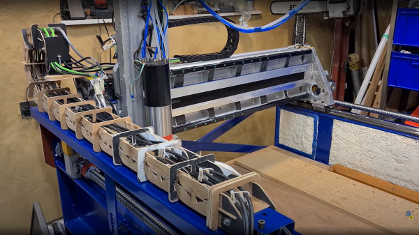
[FloweringElbow] aka [Bongo] on YouTube is certainly having a go at this, and we reckon he’s onto a winner! This epic flatbed CNC build (video, embedded below) starts with some second hand structural I-beam, with welded-on I-beam legs, DIY cast aluminium side plates and plenty of concrete to give a strong and importantly, heavy structure.
The ideal machine is as rigid as possible, and heavy, to dampen out vibrations caused by high-feed speed cutting, or the forces due to cutting harder materials, so bigger really is better. For construction of the frame, steel is pretty strong, and the mass of the structure gives it additional damping, but triangulation was needed to counteract additional twisting. He stitch-welded the pre-heated frame in inch-long sections to limit the heat transferred into the metal, minimizing the subsequent warpage. [Bongo] used hacky Vibratory stress relief (VSR) constructed from a washing machine motor and eccentric weight, clamped to the frame, with feedback from a mobile phone app to find the resonant frequencies. There are other videos on the channel devoted to that topic of such stress relief techniques.
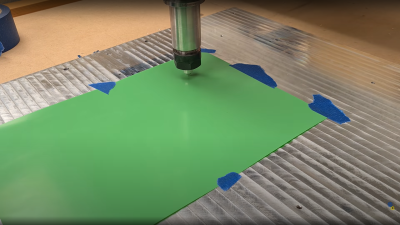
Precise enough to cut sticky-backed vinyl at half thickness!
When it came time for adding even more mass, a priming coat was made from a mixture of bonding epoxy and sharp grit, intended for non-slip flooring. The concrete mix used Portland cement, pozzolan (Silica fume) polycarboxylate superplasticiser and 1/2″ glass fiber threads. A second mix added crushed stone for additional mass. A neat trick was to make a handheld vibratory compactor from a plate welded onto the end of old drill bit, mounted in an SDS hammer drill.
Once the frame was flipped the right way up (collapsing the overloaded hoist in the process) it was necessary to level the top surface to accept the linear rails. This was done using a super runny, self-leveling epoxy, and checked by flowing water over it. Once the epoxy surfaces were adequately flat and coplanar (and much scraping later) the linear rails were attached, after creating some epoxy shoulders for them to butt up against. End plates to attach the Y axis lead screws, were added by bolting into the frame with a grit-loaded epoxy bond in between.
The gantry design was skipped for this video (but you can see that here) and once mounted a quick test showed the machine was viable. One curious task was making their own cable-chain from ply, on the machine itself, rather than buying something expensive off-the-peg. Why not? Once the machine was working well enough to mill a flat sheet of steel to nice reflective surface, it was used to mount a DIY drag-knife to cut out shapes in some vinyl, so it has the precision. We did like seeing an XBox controller used to manually jog the machine around! So much to see in this build and other related videos, we reckon this channel is one to watch!
We’ve featured CNC builds many a time, there’s a build whatever your needs and budget, but here’s a good starting point to build a machine, just good enough to build the tools you need. If you don’t happen to have a source of structural I-beam to hand, you can do something quite capable with wood, and if you fancy a go at 3D printing a knee mill, we’ve got that covered as well.
Everybody knows the trick to holding a candle flame to a balloon without it bursting — that of adding a little water before the air to absorb the heat from the relatively cool flame. So [Integza], in his quest to 3D print a jet engine wondered if the same principle could applied to a 3D printed combustion chamber. First things first, the little puddle of water was replaced with a pumped flow, from an external reservoir, giving the thin plastic inner surface at least a vague chance of survival. Whilst this whole plan might seem pretty bonkers (although we admit, not so much if you’ve seen any of other videos in the channel lately) the idea has some merit. Liquid cooling the combustion jacket is used in a great many rocket engine designs, we note, the German WWII V2 rocket used this idea with great success, along with many others. After all, some materials will only soften and become structurally weak if they get hot enough in any spot, so if it is sufficiently conductive, then the excess heat can be removed from the outer surface and keep the surface temperature within sensible bounds. Since resin is a thermoset plastic, and will burn, rather than melt, this behaviour will be different, but not necessarily better for this application.
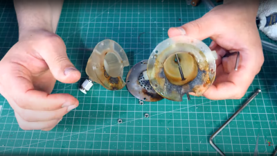
The combustion chamber itself didn’t burn
The issue we can see, is balancing the thermal conductivity of the resin wall, with the rate of cooling from the water flow, whilst making it thick enough to withstand the pressure of combustion, and any shock components. Quite a complicated task if you ask us. Is resin the right material for the job? Probably not, but it’s fun finding out anyway! In the end [Integza] managed to come up with a design, that with the help of a metal injector separator plate, survived long enough to maintain some sort of combustion, until the plate overheated and burned the resin around its support. Better luck next time!
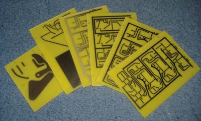
Back in November 1974 the publication “Practical Wireless” produced a five-part article series showing the reader how to construct a version of the popular “pong” game that could be played on the television screen available in the typical British home. [Grant Searle] had wanted to build this project for years, but it took him until 2008 to find the opportunity to do so. The magazine article printed PCB layouts to 1:1 scale, with a bill of materials and assembly instructions. After each month, the reader would have an assembled the project a little more, with the final month dedicated to point-to-point wiring and final setup. Subsequent months contained some enhancements such as a scoring system and sound effects, but these are not yet part of the main build. In order to understand the build, you will need to download the PDF copy of the magazines prints. (And if you’re an electronics nerd like this scribe, you’ve already done that right?)
A tidy assembly job with an authentic retro style
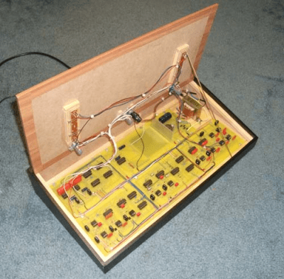
The electronics are based upon pure discrete 7400-series logic, 741 opamp-based ramp generators and, you guessed it, 555 timers. The way the various boards have discrete functions is particularly interesting. For example, in part 3, the PCB described (board A) not only is the master field/line sync generator, but also generates the video signals for the ball, with its position and size determined in an analogue fashion. Signals coming into the board from Board C (top/bottom base) cause a discrete flip-flop to toggle, changing the ball’s direction as it ‘bounces’ off the edge of the screen. Each board generates its own video signal, which are then all combined in the final video mixer (board E) that simply wire-OR’s them all with the composite sync to generate the composite video needed. This would have been tapped off and fed to a UHF video modulator, but [Grant] chose not to install that for the build. The whole thing was wrapped up inside an MDF case, coated in that dubious fake-wood plastic wrap, for that very 70’s aesthetic some of us remember fondly.
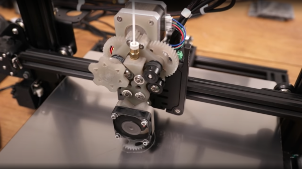
[Proper Printing] clearly enjoys pushing the boundaries of 3D printed materials, and sometimes this requires building custom 3D printers or at least the business end of them. Flexible filaments can be a bit of a pain to deal with, simply because most extruders are designed to push the filament into the hot end with a simple hobbed bolt (or pinch roller setup) and only work reliably due the rigidity of the plastic itself. Once you go flexible, the rigidity is reduced and the filament often deflects sideways and the extruder jams. The longer the filament path leading to the hotend, the harder it gets. The dual belt drive extruder (they’re calling it ‘proper extruder’) grips the filament on two sides with a pair of supported belts, guiding it into the hotend without allowing it to deflect sideways. The extruder body and gears were resin printed (but, we checked — the design is suitable for FDM printing as well) proving that resin printing on modern printers, does indeed maintain adequate dimensional accuracy allowing the building of mechanisms, despite the naysayers! Continue reading “Tame Your Flexible Filaments With This Belt-Drive Extruder”→
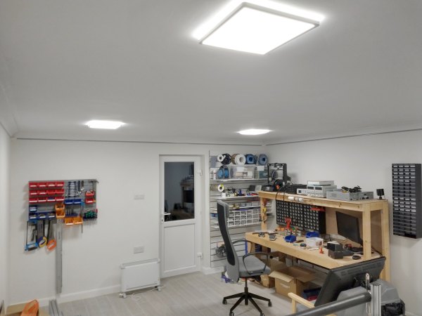
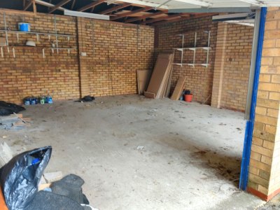
Plenty of potential, but a cozy hacking space it is not
To us hackers and makers, the tools of our trade are often as important and interesting as the details of the hacks themselves, but what about the most important tool of all — the very space you use to make your magic happen? That may be your bedroom, a nearby hackerspace, and if you have the resources, you may even own a place of your own, and get to build your perfect workspace.
The latter situation is what [MichD] and partner [Brittany] found themselves in, having moved into their first place. Many couples focus on getting a hot tub in the garden or sorting the nursery, but these two are proper electronics nerds, so they converted a free-standing double wide garage into the nerdhub, learning as they went along, and documenting it in excruciating detail for your viewing pleasure.
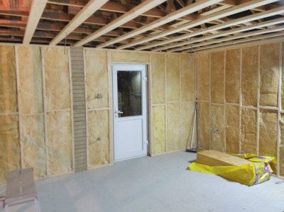
Door fitted, framed up, and insulation in place. All ready for plasterboarding.
The building structurally is a single-skinned brick-built box, with a raw concrete floor. Pretty typical stuff for the UK (we’ve seen much worse), but not ideal for spending an extended amount of time in due to our damp, cold climate, at least in winter.
The first order of business was partitioning the front section for bike storage, and screeding the floor. Once the floor was solid, the walls and ceiling joists could be framed up, ready for fitting insulation material and covering with plasterboard.
Electrics were next in order, with the wires clipped to the brickwork, well away from where the plasterboard would be, therefore making it less likely to accidentally drill into a live cable when adding external fixtures.
Since the front part of the room was to be partitioned off, another access door was needed. This involved cutting out the bricks to fit a concrete lintel. With that installed, and the bricks above supported, the area below was cut out to the required shape. A somewhat nerve-wracking experience, if you ask us!
As any self-respecting hacker will tell you — no room build is complete without a decent amount of RGB bling, so the whole room was decked out with APA102 addressable LED strips. Control of these was courtesy of WLED running on an ESP32 module, with LedFX used on a nearby PC to perform music visualisation, just because.
Conceptually, FDM 3D printing is quite a simple process: you define a set of volumes in 3D space, then the slicing software takes a cut through the model at ever-increasing heights, works out where the inner and outer walls are, and then fills in the inside volume sparsely in order to tie the walls together and support the top layers that are added at the end.
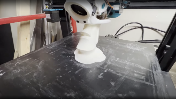
But as you will find quite quickly, when models get larger and more complex, printing times can quickly explode. One trick for large models with simple shapes but very low structural needs is to use so-called ‘vase mode’, which traces the outline of the object in a thin, vertical spiral. But this is a weak construction scheme and allows only limited modelling complexity. With that in mind, here’s [Ben Eadie] with a kind-of halfway house technique (video, embedded below) that some might find useful for saving on printing time and material.
This solid shape is mostly cut-through to make supporting ribs between the walls of the shell
The idea is to use vase mode printing, but by manipulating the shell of the model, adding partially cut-through slots around the perimeter, and critically, adding one slot that goes all the way.
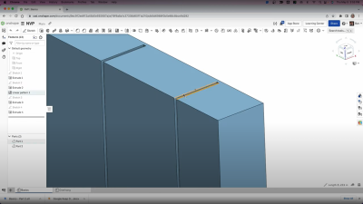
First you need a model that has an inner shell that follows the approximate shape of the outer, which you could produce by hollowing out a solid, leaving a little thickness. By making the slot width equal to half the thickness of the nozzle size and stopping the slots the same distance from the outer shell, vase mode can be used to trace the outline of shape, complete with supporting ribs in between the inner and outer walls of the shell.
Because the slot is narrower than the extrudate, the slot walls will merge together into one solid rib, tying the objects’ walls to each other, but critically, still allowing it to be printed in a continuous spiral without any traditional infill. It’s an interesting idea, that could have some merit.