Forget Sudoku, Build Yourself A Minimalist Rubik’s Solver Robot

Some people like crossword puzzles, some are serious sudoku ninjas, but [Andrea Favero] likes to keep himself sharp, by learning coding and solving control problems, and that is something we can definitely relate to. When learning a new platform, it’s a very good idea to have a substantial project or goal in mind, and learn what is needed on the way there. [Andrea] chose to build an autonomous Rubik’s cube solver, and was kind enough to document exactly how how to do it, and we’re glad of it!

The result of the openCV processing chain

Working in python with OpenCV, [Andrea] uses the methodology by [Oussama Barkouki] to process each face image and convert it into a table of the colours of individual facelets. The basics of that, are first to convert the image to grayscale, then use a gaussian blur to denoise the image. Edges are identified using the canny algorithm, the result of which is then dilated and passed into a contour detector. The contours are sent into a cunning filter that identifies square contours, and those the wrong size are filtered off. What you’re left with are the outlines of the actual coloured facelets. Once you have a list of squares, these can be used to form image masks, and thence select the average colour from each square. The colour is then quantised and stored as a labelled colour from the standard Western Rubik’s cube colour scheme. Finally, once all face images are captured and facelets colours identified, the data are passed into a Rubik’s cube solving algorithm developed by [Hegbert Kociemba,] a guide to which is available on the speedsolving site. The result of the solving step is a sequence of descrambling moves, in the move notation developed by [David Singmaster]. Fascinating stuff, if you ask us! Continue reading “Forget Sudoku, Build Yourself A Minimalist Rubik’s Solver Robot”

The Wanhao Duplicator CNC Heat Sealer

One custom, compliant heat exchanger, coming right up!

[Thane Hunt] needed to find a way to make a variety of different heat-seal patterns on a fluid heat exchanger made from polyolefin film, and didn’t want all the lead time and expense of a traditional sealing press machined from a steel plate. Pattern prototyping meant that the usual approach would not allow sufficient iteration speed and decided to take a CNC approach. Now, who can think of a common tool, capable of positioning in the X-Y plane, with a drivable Z axis and a controlled heat source? Of course, nowadays the answer is the common-or-garden FDM 3D printer. As luck would have it, [Thane] had an older machine to experiment with, so with a little bit of nozzle sanding, and a sheet of rubber on the bed, it was good to go!

Custom seal path made in Onshape

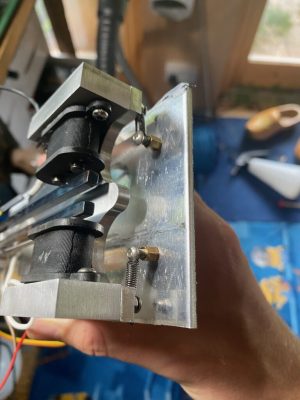
Now, heat sealing is usually done in a heated press, with a former tool, which holds the material in place and gives a flat, even seal. Obviously this CNC approach isn’t going to achieve perfect results, but for proof-of-concept, it is just fine. A sacrificial nozzle was located (but as [Thane] admits, a length of M6 would do, in a pinch) and sanded flat, and parallel to the bed, to give a 3mm diameter contact patch. A silicone rubber sheet was placed on the bed, and the polyolefin film on top. The silicone helped to hold the bottom sheet in place, and gives some Z-axis compliancy to prevent overloading the motor driver. Ideally, the printer would have been modified further to move this compliancy into the Z axis or the effector end, but that was more work. With some clever 3D modelling, Cura was manipulated to generate the desired g-code (a series of Z axis plunges along a path) and a custom heated indenter was born!

This isn’t the first such use of a 3D printer we’ve seen, here’s an earlier failure, and like everything, there’s more than one way to do it – here’s a method of making inflatable bladders with a defocused CO2 laser.

(warning! Two minutes of a 3D printer head-banging into the bed!)

Continue reading “The Wanhao Duplicator CNC Heat Sealer

Linux Arcade Cab Gives Up Its Secrets Too Easily

Sometimes reverse engineering embedded systems can be a right old faff, with you needing to resort to all kinds of tricks such as power glitching in order to poke a tiny hole in the armour, giving you an way in. And, sometimes the door is just plain wide open. This detailed exploration of an off-the-shelf retro arcade machine, is definitely in that second camp, for an unknown reason. [Matthew Alt] of VoidStar Security, took a detailed look into how this unit works, which reads as a great introduction to how embedded Linux is constructed on these minimal systems.

Could this debug serial port be more obvious?

The hardware is the usual bartop cabinet, with dual controls and an LCD display, with just enough inside a metal enclosure to drive the show. Inside this, the main PCB has the expected minimal ARM-based application processor with its supporting circuit. The processor is the Rockchip RK3128, sporting a quad-core ARM Neon and a Mali400 GPU, but the main selling point is the excellent Linux support. You’ll likely see this chip or its relatives powering cheap Android TV boxes, and it’s the core of this nice looking ‘mini PC’ platform from firefly. Maybe something to consider seeing as though Raspberry Pis are currently so hard to come by?

Anyway, we digress a little, [Matthew] breaks it down for us in a very methodical way, first by identifying the main ICs and downloading the appropriate datasheets. Next he moves on to connectors, locating an internal non-user-facing USB micro port, which is definitely going to be of interest. Finally, the rather obvious un-populated 3-pin header is clearly identified as a serial port. This was captured using a Saleae clone, to verify it indeed was a UART interface and measure the baud rate. After doing that, he hooked it into a Raspberry Pi UART and by attaching the standard screen utility to the serial device, lo-and-behold, a boot log and a root prompt! This thing really is barn-door wide-open.

Is that a root prompt you have for me? Oh why yes it is!

Simply by plugging in a USB stick, the entire flash memory was copied over, partitions and all, giving a full backup in case subsequent hacking messed things up. Being based on U-Boot, it was a trivial matter of just keying in ‘Ctrl-C’ at boot time, and he was dropped straight into the U-Boot command line, and all configuration could be easily read out. By using U-Boot to low-level dump the SPI flash to an external USB device, via a RAM copy, he proved he could do the reverse and write the same image back to flash without breaking something, so it was now possible to reverse engineer the software, make changes and write it back. Automation of the process was done using Depthcharge on the Raspberry Pi, which was also good to read about. We will keep an eye on the blog for what he does with it next!

As we’ve covered earlier, embedded Linux really is everywhere, and once you’ve got hardware access and some software support, hacking in new tricks is not so hard either.

Another Neat General Purpose Soldering Iron Driver

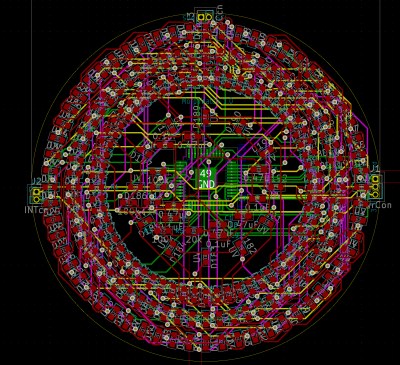
Over on Hackaday.io, user [Tomasz Jastrzebski] has designed a tidy-looking custom controller for driving temperature-controlled soldering irons. The design is intended to be general purpose, capable of operating with irons rated for different voltages and probe type, be they thermocouple- or thermistor-based. Rather than integrating a power supply, this is handled by an external unit, giving the possibility of feeding this from a variety of sources that are not necessarily tied to the grid.

Hardware-wise, we’ve got the ubiquitous STM32 microcontroller in charge of the show, with a nice front end based on the INA823 instrumentation amplifier, referenced to a REF2030 precision voltage source. The input stage is configured as a versatile Wheatstone bridge input circuit, giving plenty of scope for tweaking.

There are a few extra features in the design that aren’t necessarily needed for a soldering iron driver, such as RTC support, complete with supercapacitor backup, but then this doesn’t have to drive a soldering iron, it could drive any DC heater with temperature feedback. With a change in firmware, this could serve other tasks. One potential feature that springs to mind — have the unit automatically power down at a certain time of day in case it was left on accidentally.

The schematic has a lot of relevant detail — in that many parts have a good list of alternatives, presumably because of the semiconductor shortages — which is a good habit to get into if you ask us. Many of us involved with manufacturing have been doing this for years, as it makes sense to give the assembly house the extra options, but this really is basically mandatory practice now.

Firmware for the STM32G0 series microcontroller is based on the STM32 HAL, keeping it simple, with a Visual Studio Code project provided for your convenience. All hardware (KiCAD) and firmware can be found on the project GitHub.

We’ve seen a few projects like this over the years, like this Really Universal Soldering Controller, a custom controller for JBC irons, and this great portable Arduino-based unit.

This Parametric Project Box Generator Is Super Easy

When it comes to taking an idea from concept to prototype reality, depending on the type of project, there can be quite a few sub-tasks along the way. Take for example, your latest electronic widget design. You’ve finished the schematic, and the PCB layout is a work of art (if you do say so yourself) but having that kicking around on the desk unprotected with wires dangling is not the end game. Now you’ve got to make an enclosure of some kind, and I don’t know about you, but this is the bit where this scribe struggles a little to get something to fit nice. Even if you’ve got the latest 3D printer dialed in to within a gnat’s whisker of perfection, you’ve still got to come up with the design, and those dimensions need to be really accurate. So, for those of us who are great at the PCB, but suck at the enclosure, [Willem Aandewiel] has been busy making the tool just for you, with his PCB-orientated Yet Another Parametric Projectbox generator (YAPP.)

Defining the PCB mounting points w.r.t. the PCB outline

Without hesitation you can head over to the YAPP GitHub, grab that sweet OpenSCAD code, and get cracking with the demos. Provided for your convenience are a number of examples for enclosing some common items, such as Arduinos and ESP32 modules, so you can use those as a springboard to get your own code in place. YAPP works based off the PCB — by specifying programmatically since this is OpenSCAD — outer dimensions, mounting post locations first. Next you define openings in the six faces of the box, and the tool happily spits out a platter with the base and lid ready to drop into Cura (or your slicer of choice) What could be easier?

End face cutouts

And before you start on non-rectangular designs, this is a rectangular box generator for rectangular PCBs. That is all this is designed for, and as far as we can tell, it does that one job well.

Of course, this is by no means the first enclosure generator to grace these pages, far from it. Here’s one for starters. If you’re here for tips to help make better designs, check this out, and finally 3DHubs also has a nice guide for you. Happy printing!

Remoticon 2021 // Voja Antonic Makes You A Digital Designer

[Voja Antonic] has been building digital computers since before many of us were born. He designed with the Z80 when it was new, and has decades of freelance embedded experience, so when he takes the time to present a talk for us, it’s worth paying attention.

For his Remoticon 2022 presentation, he will attempt to teach us how to become a hardware expert in under forty minutes. Well, mostly the digital stuff, but that’s enough for one session if you ask us. [Voja] takes us from the very basics of logic gates, through combinatorial circuits, sequential circuits, finally culminating in the description of a general-purpose microprocessor.

A 4-bit ripple-carry adder with additional CPU flag outputs

As he demonstrates, complex digital electronics systems really are just built up in a series of steps of increasing complexity. starting with individual active elements (transistors operating as switches) forming logic elements capable of performing simple operations.

From there, higher level functions such as adders can be formed, and from those an ALU and so on. Conceptually, memory elements can be formed from logic gates, but it’s not the most efficient way to do it, and those tend to be made with a smaller and faster circuit. But anyway, that model is fine for descriptive purposes.

Once you have combinatorial logic circuits and memory elements, you have all you need to make the necessary decoders, sequencers and memory circuits to build processors and other kinds of higher complexity circuits.

Obviously forty minutes isn’t anywhere nearly enough time time to learn all of the intricacies of building a real microprocessor like the pesky details of interfacing with it and programming it, but for getting up the learning curve from just a knowledge of binary numbers to an understanding of how a CPU is built, it’s a pretty good starting point.

Now, If you can only tear your eyes away from his slick game-of-life wall mounted LED display, you might pick up a thing or two.

Continue reading “Remoticon 2021 // Voja Antonic Makes You A Digital Designer”

Reverse Engineering: Trash Printer Gives Up Its Control Panel Secrets

Many of us hardware-oriented types find it hard to walk past a lonely-looking discarded item of consumer electronics without thinking “If only I could lug that back to the car and take it home to play with” and [phooky] from NYC Resistor is no stranger to this sentiment. An old Epson WF-2540 inkjet printer was disassembled for its important ‘nutrients,’ you know, the good stuff like funky motors, encoders and switches. But what do you do with the control panel? After all, they’re usually very specific to the needs of the device they control, and don’t usually offer up much scope for reuse.

The RP2040 PIO is quite capable of pushing out those LCD pixels

[phooky] doesn’t usually bother with them, but this time decided to have a crack at it for fun. Inside, nothing out of the ordinary, with a large single-sided PCB for the key switches and LEDs, and a small PCB hosting the LCD display. The easy part was to figure out how the keyboard scanning was done, which turned out to be pretty simple, it just uses some 74-series shift register devices to scan the columns and clock out the row lines. A Raspberry Pi Pico module was pressed into service to scan the keyboard and enable a keyboard map to be created, by pure brute-force. No need to trace the circuit.

Things got interesting when [phooky] started looking into the LCD interface, based on the Epson E02A46EA chip (good luck finding a datasheet for that one!) and quickly realised that documentation simply wasn’t available, and it would be necessary to do things the hard way. Poking around the lines from the main CPU (an Epson E01A9CA , whatever that is) the display clock was identified, as well as some control signals, and three lines for the RGB channels. By throwing a Saleae data capture into some ROM exploring software, the display configuration was determined to be a standard 320×120 unit.

The PIO unit of the RP2040 was used to generate the video waveforms and push the pixels out to the LCD controller, allowing the RP2040 board to be wired inside the case permanently, converting the control panel into a USB device ready for action!

Want to know a little more about reverse engineering junk (or not) items and repurposing them to your will? Checkout this hacking piece from a couple of weeks back. For something a little more advanced, you could try your hand at a spot of car ECU hacking.

Thanks [Perry] for the tip!