Whilst microwave plasmas are nothing new around here, we were curious to see what happens at 20x the power, and since YouTuber [Styropyro] had put out a new video, we couldn’t resist seeing where this was going. Clearly, as your bog standard microwave oven can only handle at most one kilowatt; the ‘oven’ needed a bit of an upgrade.
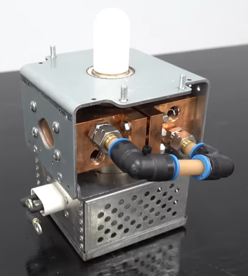
Getting hold of bigger magnetrons is tricky, but as luck — or perhaps fate — would have it, a 16 kW, water-cooled beast became available on eBay thanks to a tip from a Discord user. It was odd but perhaps not surprising that this Hitatch H0915 magnetron was being sold as a ‘heat exchanger.’
[Styropyro] doesn’t go into much detail on how to supply the anode with its specified 16 kW at 9.5 kVDC, but the usual sketchy (well down-right terrifying) transformers in the background indicate that he had just what was needed kicking around the ‘shop. Obviously, since this is a [Styropyro] video, these sorts of practical things have been discussed before, so there is no need to waste precious time and get right on to blowing stuff up!
Some classic microwave tricks are shown, like boiling water in five seconds, cooking pickles (they really do scream at 20 kW) and the grape-induced plasma-in-a-jar. It was quite clear that at this power level, containing that angry-looking plasma was quite a challenge. If it was permitted to leak out for only a few seconds, it destroyed the mica waveguide cover and risked coupling into the magnetron and frying it. Many experiments followed, a lot of which seemed to involve the production of toxic brown-colored nitrogen dioxide fumes. It was definitely good to see him wearing a respirator for this reason alone!
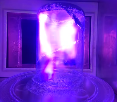
The main star of the demonstration was the plasma-induced emissions of various metal elements, with the rare indigo and violet colors making an appearance once the right blend of materials was introduced into the glassware. Talking of glassware, we reckon he got through a whole kitchen’s worth. We lost count of the number of exploded beakers and smashed plates. Anyway, plasma science is fun science, but obviously, please don’t try any of this at home!
For those who didn’t take an ‘electron devices’ course at college, here’s a quick guide to how magnetrons work. Plasma physics is weird; here’s how the plasma grape experiment works. Finally, this old hack is a truly terrible idea. Really don’t do this.