No Active Components In This Mysterious Audio Oscillator

What’s the simplest audio frequency oscillator you can imagine? There’s the 555, of course, and we can think of a few designs using just two transistors or even a few with just one. But how about an oscillator with no active components? Now there’s a neat trick.

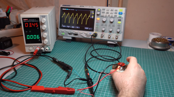
Replicating [Stelian]’s “simplest audio oscillator on the Internet” might take some doing on your part, since it relies on finding an old telephone. Like, really old — you’ll need one with the carbon granule cartridge in the handset, along with the speaker. Other than that, all you’ll need is a couple of 1.5-volt batteries, wiring everything in one big series loop, and placing the microphone and speaker right on top of each other. Apply power and you’re off to the races. [Stelian]’s specific setup yielded a 2.4-kHz tone that could be altered a bit by repositioning the speaker relative to the mic. On the oscilloscope, the waveform is a pretty heavily distorted sine wave.

It’s a bit of a mystery to [Stelian] as to how this works without something to provide at least a little gain. Perhaps the enclosure of the speaker or the mic has a paraboloid shape that amplifies the sound just enough to kick things off? Bah, who knows? Let the hand-waving begin!

Continue reading “No Active Components In This Mysterious Audio Oscillator”

Reverse Engineering The Quansheng Hardware

In the world of cheap amateur radio transceivers, the Quansheng UV-K5 can’t be beaten for hackability. But pretty much every hack we’ve seen so far focuses on the firmware. What about the hardware?

To answer that question, [mentalDetector] enlisted the help of a few compatriots and vivisected a UV-K5 to find out what makes it tick. The result is a complete hardware description of the radio, including schematics, PCB design files, and 3D renders. The radio was a malfunctioning unit that was donated by collaborator [Manuel], who desoldered all the components and measured which ones he could to determine specific values. The parts that resisted his investigations got bundled up along with the stripped PCB to [mentalDetector], who used a NanoVNA to characterize them as well as possible. Documentation was up to collaborator [Ludwich], who also made tweaks to the schematic as it developed.

PCB reverse engineering was pretty intense. The front and back of the PCB — rev 1.4, for those playing along at home — were carefully photographed before getting the sandpaper treatment to reveal the inner two layers. The result was a series of high-resolution photos that were aligned to show which traces connected to which components or vias, which led to the finished schematics. There are still a few unknown components, The schematic has a few components crossed out, mostly capacitors by the look of it, representing unpopulated pads on the PCB.

Hats off to the team for the work here, which should make hardware hacks on the radio much easier. We’re looking forward to what’ll come from this effort. If you want to check out some of the firmware exploits that have already been accomplished on this radio, check out the Trojan Pong upgrade, or the possibilities of band expansion. We’ve also seen a mixed hardware-firmware upgrade that really shines.

Ancient Cable Modem Reveals Its RF Secrets

Most reverse engineering projects we see around here have some sort of practical endpoint in mind. Usually, but not always. Reverse-engineering a 40-year-old cable modem probably serves no practical end, except for the simple pleasure of understanding how 1980s tech worked.

You’ll be forgiven if the NABU Network, the source of the modem [Jared Boone] tears into, sounds unfamiliar; it only existed from 1982 to 1985 and primarily operated in Ottawa, Canada. It’s pretty interesting though, especially the Z80-based computer that was part of the package. The modem itself is a boxy affair bearing all the hallmarks of 1980s tech. [Jared]’s inspection revealed a power supply with a big transformer, a main logic board, and a mysterious shielded section with all the RF circuits, which is the focus of the video below.

Using a signal generator, a spectrum analyzer, and an oscilloscope, not to mention the PCB silkscreen and component markings, [Jared] built a block diagram of the circuit and determined the important frequencies for things like the local oscillator. He worked through the RF section, discovering what each compartment does, with the most interesting one probably being the quadrature demodulator. But things took a decidedly digital twist in the last compartment, where the modulated RF is turned into digital data with a couple of 7400-series chips, some comparators, and a crystal oscillator.

This tour of 80s tech and the methods [Jared] used to figure out what’s going on in this box were pretty impressive. There’s more to come on this project, including recreating the original signal with SDRs. In the mean time, if this put you in the mood for other videotext systems of the 80s, you might enjoy this Minitel terminal teardown.

Continue reading “Ancient Cable Modem Reveals Its RF Secrets”

Hackaday Links Column Banner

Hackaday Links: April 21, 2024

Do humanoid robots dream of electric retirement? Who knows, but maybe we can ask Boston Dynamics’ Atlas HD, which was officially retired this week. The humanoid robot, notable for its warehouse Parkour and sweet dance moves, never went into production, at least not as far as we know. Atlas always seemed like it was intended to be an R&D platform, to see what was possible for a humanoid robot, and in that way it had a heck of a career. But it’s probably a good thing that fleets of Atlas robots aren’t wandering around shop floors or serving drinks, especially given the number of hydraulic blowouts the robot suffered. That also seems to be one of the lessons Boston Dynamics learned, since Atlas’ younger, nimbler replacement is said to be all-electric. From the thumbnail, the new kid already seems pretty scarred and battered, so here’s hoping we get to see some all-electric robot fails soon.

Continue reading “Hackaday Links: April 21, 2024”

Solar Panel Keeps Cheap Digital Calipers Powered Up

There’s no doubt that cheap digital calipers are useful, especially when designing 3D-printed parts. Unfortunately, cheap digital calipers are also cheap, and tend to burn through batteries quickly. Sure, you can remove the battery when you’re done using them, but that’s for suckers — winners turn to solar power to keep their calipers always at the ready.

[Johan]’s solar upgrade begins with, unsurprisingly, a solar cell, one that just fits on the back of his digital calipers. Like most of these cheap calipers, this one is powered by a single 1.5 V LR44 button cell, while the polycrystalline solar cell is rated for 5 V, so [Johan] used a red LED as a crude voltage regulator. He also added a stack of fourteen 100 μF SMD capacitors soldered together in parallel. The 1206 devices form a 1,400 μF block that’s smaller than the original button cell so that everything fits in the vacated battery compartment. It’s pretty slick.

Given their agreeable price point, digital calipers are a tempting target for hacking. We’ve seen a ton of them, from accessibility add-ons to WiFi connectivity and even repurposing them for use as DROs. Ever wonder how these things work? We’ve looked at that, too.

Hacked Oscilloscope Plays Breakout, Hints At More

You know things are getting real when the Dremel is one of the first tools you turn to after unboxing your new oscilloscope. But when your goal is to hack the scope to play Breakout, sometimes plastic needs to be sacrificed.

Granted, the scope in question, a Fnirsi DSO152, only cost [David Given] from Poking Technology a couple of bucks. And while the little instrument really isn’t that bad inside, it’s limited to a single channel and 200 kHz of bandwidth, so it’s not exactly lab quality. The big attractions for [David] were the CH32F103 microcontroller and the prominent debug port inside, not to mention the large color LCD panel.

[David]’s attack began with the debug port and case mods to allow access, but quickly ground to a halt when he accidentally erased the original firmware. But no matter — tracing out the pins is always an option. [David] made that easier by overlaying large photos of both sides of the board, which let him figure out which buttons went to which pins, and mapping for the display’s parallel interface. He didn’t mess with any of the analog stuff except to create a quick “Hello, oscilloscope!” program to output a square wave to the calibration pin. He did, however, create a display driver and port a game of breakout to the scope — video after the hop.

We’ve been seeing a lot of buzz around the CH32xx MCUs lately; seeing it start to show up in retail products is perhaps a leading indicator of where the cheap RISC chips are headed. We’ve seen a few interesting hacks with them, but we’ve also heard tell they can be hard to come by. Maybe getting one of these scopes to tear apart can fix that, though.

Continue reading “Hacked Oscilloscope Plays Breakout, Hints At More”

More Microwave Metal Casting

If you think you can’t do investment casting because you don’t have a safe place to melt metal, think again. Metal casting in the kitchen is possible, as demonstrated by this over-the-top bathroom hook repair using a microwave forge.

Now, just because it’s possible doesn’t mean it’s advisable. There are a lot better ways to fix something as mundane as a broken bathroom hook, as [Denny] readily admits in the video below. But he’s been at the whole kitchen forging thing since building his microwave oven forge, which uses a special but easily constructed ceramic heat chamber to hold a silicon carbide crucible. So casting a replacement hook from brass seemed like a nice exercise.

The casting process starts with a 3D-printed model of the missing peg, which gets accessories such as a pouring sprue and a thread-forming screw attached to it with cheese wax. This goes into a 3D-printed mold which is filled with a refractory investment mix of plaster and sand. The green mold is put in an air fryer to dry, then wrapped in aluminum foil to protect it while the PLA is baked out in the microwave. Scrap brass gets its turn in the microwave before being poured into the mold, which is sitting in [Denny]’s vacuum casting rig.

The whole thing is over in seconds, and the results are pretty impressive. The vacuum rig ensures metal fills the mold evenly without voids or gaps. The brass even fills in around the screw, leaving a perfect internal thread. A little polishing and the peg is ready for bathroom duty. Overly complicated? Perhaps, but [Denny] clearly benefits from the practice jobs like this offer, and the look is pretty cool too. Still, we’d probably want to do this in the garage rather than the kitchen.
Continue reading “More Microwave Metal Casting”