Hackaday Prize 2023: An Agricultural Robot That Looks Ready For The Field

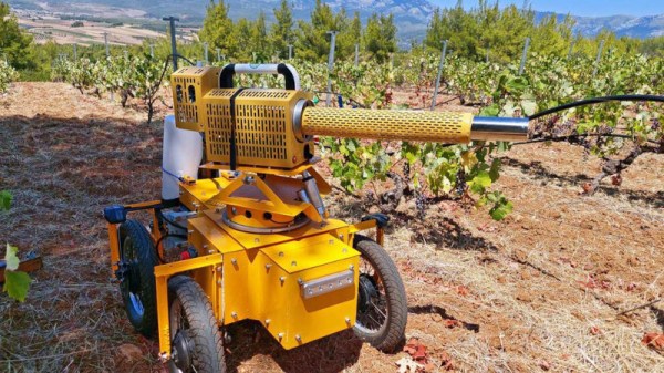
In the world of agriculture, not all enterprises are large arable cropland affairs upon which tractors do their work traversing strip by strip under the hot sun. Many farms raise far more intensive crops on a much smaller scale, and across varying terrain. When it comes to automation these farms offer their own special challenges, but with the benefit of a smaller machine reducing some of the engineering tasks. There’s an entry in this year’s Hackaday prize which typifies this, [KP]’s Agrofelis robot is a small four-wheeled carrier platform designed to deliver autonomous help on smaller farms. It’s shown servicing a vineyard with probably one of the most bad-ass pictures you could think of as a pesticide duster on its implement platform makes it look for all the world like a futuristic weapon.

A sturdy tubular frame houses the battery bank and brains, while motive power is provided by four bicycle derived motorized wheels with disk brakes. Interestingly this machine steers mechanically rather than the skid-steering found in so many such platforms. On top is a two degrees of freedom rotating mount which serves as the implement system — akin to a 3-point linkage on a tractor. This is the basis of the bad-ass pesticide duster turret mentioned above. Running it all is a Nvidia Jetson Nano, with input from a range of sensors including global positioning and LIDAR.

The attention to detail in this agricultural robot is clearly very high, and we could see machines like it becoming indispensable in the coming decades. Many tasks on a small farm are time-consuming and involve carrying or wheeling a small machine around performing the same task over and over. Something like this could take that load off the farmer. We’ve been there, and sure would appreciate something to do the job.

While we’re on the subject of farm robots, this one’s not the only Prize entry this year.

The Magic Of A Diode Sampler To Increase Oscilloscope Bandwidth

Making an oscilloscope is relatively easy, while making a very fast oscilloscope is hard. There’s a trick that converts a mundane instrument into a very fast one, it’s been around since the 1950s, and [CuriousMarc] has a video explaining it with an instrument from the 1960s. The diode sampler is the electronic equivalent of a stroboscope, capturing parts of multiple cycle of a waveform to give a much-slowed-down representation of it on the screen. How it works is both extremely simple, and also exceptionally clever as some genius-level high-speed tricks are used to push it to the limit. We’ve put the video below the break.

[Marc] has a Keysight 100 MHz ‘scope and the sampler allows him to use it to show 4 GHz. Inside the instrument is a pair of sample-and-hold circuits using fast diodes as RF switches, triggered by very low-rise-time short pulses. Clever tricks abound, such as using the diode pair to cancel out pulse leakage finding its way back to the source. To complete this black magic, an RF-tuned stub is utilized to help filter the pulses and further remove slower components.

It’s slightly amusing to note that the Keysight 100 MHz ‘scope is now “slow” while the early sampling ‘scopes had their “fast” capabilities in that range. The same technique is still used today, in fact, you probably have one on your bench.

The sampler he’s showing us is an accessory for another instrument we’ve previously shown you his work with.

Continue reading “The Magic Of A Diode Sampler To Increase Oscilloscope Bandwidth”

CNC Soldering Bot Handles Your Headers

Soldering pin headers by hand is a tedious task, especially when your project has a huge number of them. [iforce2d] has a large number of boards with a lot of headers, and has created a rather special CNC machine to to do the job. It’s a soldering robot, controlled by LinuxCNC and you can see it below the break.

Superficially it resembles a 3D printer made in aluminium, with an X-Y movable table and a Z-direction represented by a soldering iron and solder feeder on an arm. The solder feeder uses a Bowden tube, with a 3D-printer extruder motor pushing the solder wire down a PTFE tube and finally into a fine aluminium tube from which it’s fed to the iron tip.

Though he’s done a beautiful job of it, creating the machine is not all that’s required, because the tool path requires more attention than simply moving the iron to each pin and supplying some solder. There’s a need to consider the effect of that heat, how much each pad needs, and how much neighbouring pads contribute.

We’ve had repetitive soldering tasks just like this one though not on this scale, so we can understand the tedium this machine will relieve. We can’t however help being reminded of XKCD 1319.

Continue reading “CNC Soldering Bot Handles Your Headers”

Retrotechtacular: How Communism Made Televisions

For those of us who lived through the Cold War, there’s still an air of mystery as to what it was like on the Communist side. As Uncle Sam’s F-111s cruised slowly in to land above our heads in our sleepy Oxfordshire village it was at the same time very real and immediate, yet also distant. Other than being told how fortunate we were to be capitalists while those on the communist side lived lives of mindless drudgery under their authoritarian boot heel, we knew nothing of the people on the other side of the Wall, and God knows what they were told about us. It’s thus interesting on more than one level to find a promotional film from the mid 1970s showcasing VEB Fernsehgerätewerk Stassfurt (German, Anglophones will need to enable subtitle translation), the factory which produced televisions for East Germans. It provides a pretty comprehensive look at how a 1970s TV set was made, gives us a gateway into the East German consumer electronics business as a whole, and a chance to see how the East Germany preferred to see itself.

Black and white photograph of a display of televisions displaying a DDR Deutsche Frensehfunk logo, with an attendant adjusting one of the sets.
The RFT range of televisions in the Städtisches Kaufhaus exhibition center for the 1968 Leipzig Spring Fair. Bundesarchiv, CC-BY-SA 3.0

The sets in question are not too dissimilar to those you would have found from comparable west European manufacturers in the same period, though maybe a few things such as the use of a tube output stage and the lack of integrated circuits hints at their being a few years behind the latest from the likes of Philips or ITT by 1975. The circuit boards are assembled onto a metal chassis which would have probably been “live” as the set would have derived its power supply by rectifying the mains directly, and we follow the production chain as they are thoroughly checked, aligned, and tested. This plant produces both colour and back-and-white receivers, and since most of what we see appears to be from the black-and-white production we’re guessing that here’s the main difference between East and West’s TV consumers in the mid ’70s.

The film is at pains to talk about the factory as a part of the idealised community of a socialist state, and we’re given a tour of the workers’ facilities to a backdrop of some choice pieces of music. References to the collective and some of the Communist apparatus abound, and finally we’re shown the factory’s Order of Karl Marx. As far as it goes then we Westerners finally get to see the lives of each genosse, but only through an authorised lens. Continue reading “Retrotechtacular: How Communism Made Televisions”

Hackaday Prize 2023: This Differential Scope Probe Is Smarter Than It Looks

A differential probe, a device for measuring the voltage between two points in a circuit rather than the voltage between a point and ground, it an extremely useful addition to any electronics bench. Inside such a probe you’ll usually find a fancy op-amp working as a differential amplifier, and for correct operation they require careful adjustment to null out DC bias and achieve the maximum common mode rejection. We particularly like [Craig D]’s probe, because these adjustments are taken care of automatically by a microcontroller.

The analogue path provides a lesson for anyone interested in instrumentation signal path design, with the signal conditioning and compensation circuits feeding an AD8130 differential amplifier. Another amplifier samples the output voltage and feeds it to the ADC in the microcontroller. Common mode adjustment is taken care of by a digital potentiometer chip, and DC offset by the microcontroller’s DAC. Controlling all this is an ATSAMD10 chip, and the power is derived from the scope’s USB interface.

All in all it’s an extremely well-executed device, and one we’d be happy to have on our bench at any time. It’s by no means the first differential probe we’ve brought you, here’s another.


Proper Video, From An ESP32

Back in the day a miniature television, probably on a wristwatch, was the stuff of science fiction. Now, it’s something which can be done with a commodity microcontroller, as [Atomic14] shows us with the ESP32-TV that plays both video and sound. Even with modern silicon it’s still somewhat pushing the envelope.

As he explains in the video below the break, not all formats are simple enough to be decoded on the fly by a microcontroller. But he finds an AVI file to be within its capabilities which can be created with a bit of ffmpeg wizardry. The board is a fairly standard ESP32 device with an I2C bus, and the video stream isn’t too fast for this meager interface. You’ll maybe recognize the Muppets clip, but it’s possible that the early-80s BBC comedy staple The Young Ones might have passed you by if you’re not British.

We think this code is likely to be of use in quite a few projects, and it would be great to see it further refined. Small video players for not a lot of money can never be a bad thing.

Previous ESP32 video projects which have appeared on these pages have been more likely to involve driving a display directly.

Continue reading “Proper Video, From An ESP32”

Hackaday Prize 2023: An Anti-Tremor Handle, With No Electronics

Many of us will have seen the various active assistive devices which have appeared over the last few years to help people with a hand tremor. Probably the best known was a fork with a set of servos and an accelerometer, that kept the end of the utensil steady despite the owner’s hand movements. It’s a field which has the potential to help many people, but it’s undeniable that such technology comes with a cost.

What if the same effect could be achieved passively, without all those electronics? It’s something [Jacob] is investigating with his mechanical anti-tremor cup handle. It’s a university project completed as part of his studies so it’s very much a work-in-progress which if we’re being fair isn’t quite there yet, but we think the potential in this idea of bringing a useful assistive device at least bears further attention.

The write-up is available as a Norwegian PDF file so takes a little bit of Google Translate cut and pasting for an Anglophone. Sadly due to what must be report format requirements set by the university it’s long on procedure and shorter on engineering calculations than we’d like, but there’s an attempt to calculate the properties of the helical springs in each of the joints to match the likely forces. Our intuition is that the design as shown would require significantly more mass on the end of it than that of the mug and beverage alone to achieve some form of stability, but despite that as we said it’s an interesting enough idea that it deserves more thought.

Hand tremor assistive devices have appeared more than once on these pages before, here’s one for soldering that enlists the aid of a camera gimbal.