If you have a modern function generator on your bench it is quite likely to contain a direct-digital synthesis circuit that creates arbitrary waveforms using a microprocessor controlled DAC. If you have a cheap function generator it’s likely to contain a one-chip solution that generates approximations to sine and triangle waveforms through modifying a square wave with a set of filters.
These methods both produce adequate waveforms for most of your function generator needs, but they are both far from perfect for the purist. Both methods introduce some distortion, and to address this [michal777] has produced a generator that takes the process back to basics with all stages implemented using building block ICs and transistors. The circuit follows the same square-wave-modifying path as the cheaper integrated devices, but with significant attention paid to the design to ensure that it does as good a job as possible. It also makes for a fascinating dive into function generator design.
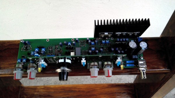
The generator hardware has been neatly fitted onto a PCB with a riser for a set of front panel controls. He shares a few pictures of previous designs. We particularly like one that appears to have been fitted into a redundant cooking pot.
We’ve brought you a few function generators over the years. If you’ve got one of the cheaper examples, we’ve even covered how you might improve it a little.