When we mention vacuum technology, it’s not impossible that many of you will instantly turn your minds to vacuum tubes, and think about triodes, or pentodes. But while there is a lot to interest the curious in the electronics of yesteryear, they are not the only facet of vacuum technology that should capture your attention.
 When [Alan Yates] gave his talk at the 2017 Hackaday Superconference entitled “Introduction To Vacuum Technology”, he was speaking in a much more literal sense. Instead of a technology that happens to use a vacuum, his subject was the technologies surrounding working with vacuums; examining the equipment and terminology surrounding them while remaining within the bounds of what is possible for the experimenter. You can watch it yourself below the break, or read on for our precis.
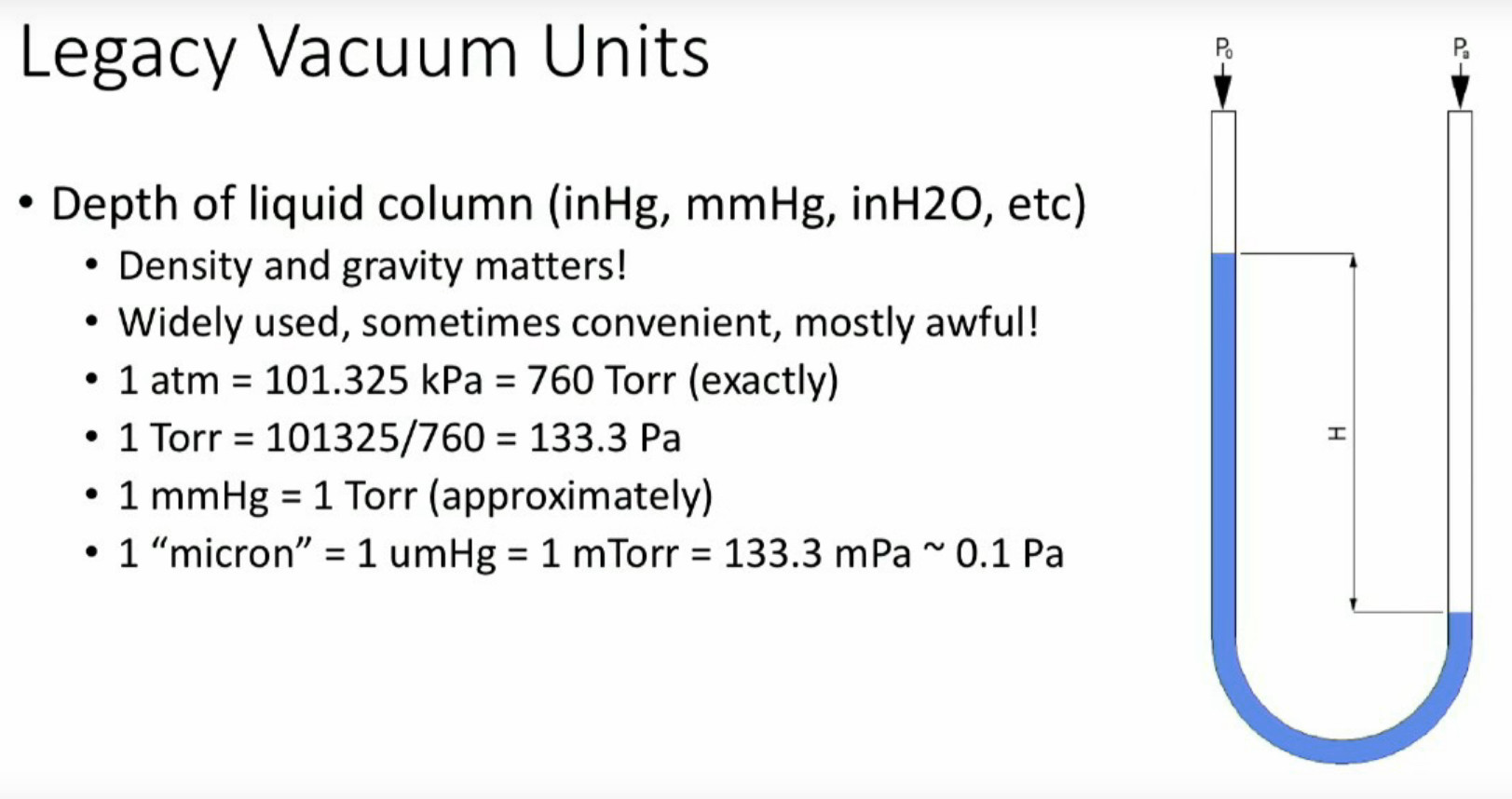
In the first instance, he introduces us to the concept of a vacuum, starting with the work of [Evangelista Torricelli] on mercury barometers in the 17th century Italy, and continuing to explain how pressure, and thus vacuum, is quantified. Along the way, he informs us that a Pascal can be explained in layman’s terms as roughly the pressure exerted by an American dollar bill on the hand of someone holding it, and introduces us to a few legacy units of vacuum measurement.
In classifying the different types of vacuum he starts with weak vacuum sources such as a domestic vacuum cleaner and goes on to say that the vacuum he’s dealing with is classified as medium, between 3kPa and 100mPa. Higher vacuum is beyond the capabilities of the equipment available outside high-end laboratories.
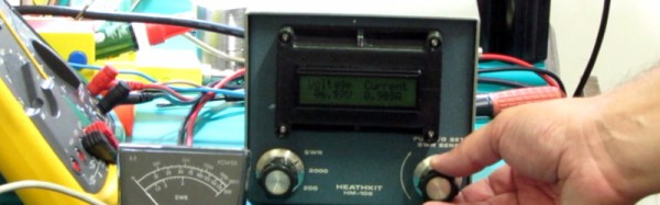
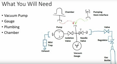 Introduction over, he starts on the subject of equipment with a quick word about safety, before giving an overview of the components a typical small-scale vacuum experimenter’s set-up. We see the different types of vacuum gauges, we’re introduced to two different types of service pumps for air conditioning engineers, and we learn about vacuum manifolds. Tips such as smelling the oil in a vacuum pump to assess its quality are mentioned, and how to make a simple mist trap for a cheaper pump. There is a fascinating description of the more exotic pumps for higher vacuums, even though these will be out of reach of the experimenter it is still of great interest to have some exposure to them. He takes us through vacuum chambers, with a warning against cheap bell jars not intended for vacuum use, but suggests that some preserving jars can make an adequate chamber.
We are then introduced to home-made gas discharge tubes, showing us a home-made one that lights up simply by proximity to a high voltage source. Something as simple as one of the cheap Tesla coil kits to be found online can be enough to excite these tubes, giving a simple project for the vacuum experimenter that delivers quick results.
Finally, we’re taken through some of the tools and sundries of the vacuum experimenter, the different types of gas torches for glass work, and consumables such as vacuum grease. Some of them aren’t cheap, but notwithstanding those, he shows us that vacuum experiments can be made within a reasonable budget.
Continue reading “Alan Yates: Introduction To Vacuum Technology”

![[M0CVO]'s Tweet that started it all](https://hackaday.com/wp-content/uploads/2017/10/screenshot-2017-10-31-nigel-booth-on-twitter.png)
![The Chrysler gas turbine car from [Brian]'s article. CZmarlin [Public domain].](https://hackaday.com/wp-content/uploads/2017/08/turbine.jpg)
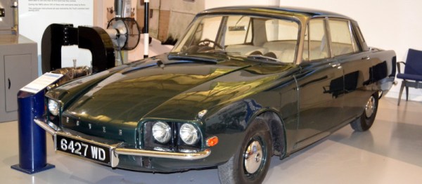
![The Rover Jet1 prototype. Allen Watkin [CC BY-SA 2.0].](https://hackaday.com/wp-content/uploads/2017/11/rover_sort_of-_2398190117.jpg)
![The Rover-BRM racing car at Gaydon. David Merrett [CC BY 2.0].](https://hackaday.com/wp-content/uploads/2017/11/1024px-rover_brm_-_gas_turbine_heritage_motor_centre_gaydon_1.jpg)