If you ever encounter railroad or railway enthusiasts, you may have heard the view that at some point in the past there was a golden age of rail transport that has somehow been lost. It’s something that’s up for debate as to when that age was or even whether with a selection of new super-high-speed trains snaking across our continents we’re in a golden age now, but it’s true to say that the rail business has had its fair share of decline in the last half-century.
It’s quite likely that when they talk of a golden age, they really mean a golden age of steam rail transport. At which point depending on where you live in the world it’s easier to put your finger on a decade. For UK residents a good candidate would be the 1930s; steam locomotive design had reached its peak, the rail network hadn’t been worn out by the demands of wartime, and private car ownership hadn’t eaten into their passenger numbers. The country was divided up into a set of regional rail monopolies, each of which had their own locomotive works and designers who were in fierce competition to show that their machines were the best and the fastest.
The LMS, the London Midland and Scottish railway company, served the northwestern segment of the country, North Wales, and the West of Scotland. Their high-speed express trains were in hot competition with those of the LNER, the London and North Eastern Railway, who served the eastern side of the country, to offer the fastest service from London to Scotland. It’s difficult to grasp through an 80-year lens, but this battle was one of national excitement, with the fastest locomotives becoming household names nationwide. The railway companies were justifiably proud of their engineering expertise, and so featured their locomotives as a key part of their marketing to the general public.
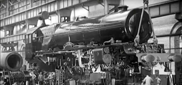
And so we come to the subject of today’s Retrotechtacular piece, a film below the break from 1935 following the construction of a high-speed express locomotive from start to finish in the LMS’s Crewe railway works. 6207 was one of a class of thirteen 4-6-2 Pacific locomotives designed by the company’s chief engineer [William Stanier], built between 1932 and 1935 and known as the Princess Royal class, all being named for princesses. In the film we see the various parts of the locomotive being cut, cast and forged from raw metal before being assembled in the Crewe plant. All the machinery is human controlled, and one of the surprises is sometimes the number of people involved in each task. The level of skill and experience in precision metalworking to be found in plants like Crewe was immense, and in some cases it is very difficult to find its equivalent in our own time.