RAMPS Rebuild Keeps Robox 3D Printer Out Of Junk Bin

A 3D printer is a wonderful invention, but it needs maintenance like every machine that runs for long hours. [Rob Ward] had a well-used Robox 3D printer that was in need of some repairs, but getting the necessary replacement parts shipped to Australia was cost-prohibitive. Rather than see a beloved printer be scrapped as e-waste, he decided to rebuild it using components that he could more easily source. Unfortunately the proprietary software and design of the Robox made this a bit difficult, so it was decided a brain transplant was the best path forward.

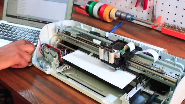
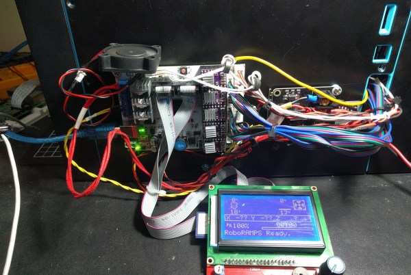
Step one was to deduce how the motors worked. A spare RAMPS 1.4 board and Arduino Mega2560 made short work of the limit switches and XYZ motors. This was largely accomplished by splicing into the PCBs themselves. The Bowden filament driver motor had a filament detector and an optical travel sensor that required a bit of extra tuning, but now the challenging task was next: extruding.

The printer’s new custom hotend.

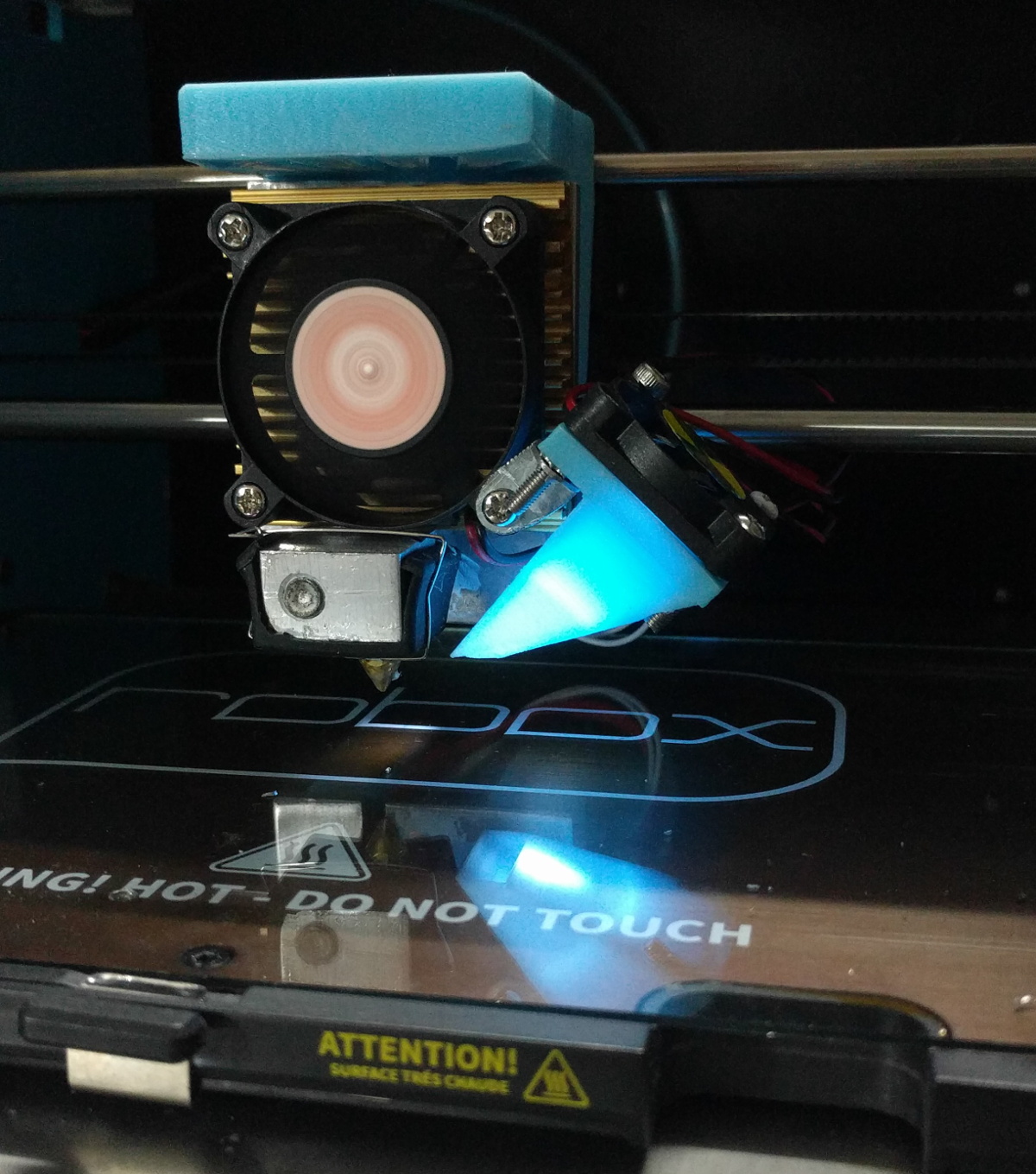
With a cheap CR10 hot end from an online auction house, [Rob] began modifying the filament feed to feed in a different direction than the Robox was designed for (the filament comes in at a 90-degree angle on the stock Robox). A fan was needed to cool the filament feed line. Initial results were mixed with lots of blockages and clogs in the filament. A better hot end and a machined aluminum bracket for a smoother path made more reliable prints.

The original bed heater was an excellent heater but it was a 240 VAC heater. Reluctant to having high voltages running through his hacked system, he switched them out for 12 VDC adhesive pads. A MOSFET and MOSFET buffer allowed the bed to reach a temperature workable for PLA. [Rob] upgraded to a GT2560 running Marlin 2.x.x.

With a reliable machine, [Rob] stepped back to admire his work. However, the conversion to the feed being perpendicular to the bed surface had reduced his overall build height. With some modeling in OpenSCAD and some clever use of a standard silicone sock, he had a solution that fed the wire into the back of the hot end, allowing to reclaim some of the build height.

It was a long twelves months of work but the write-up is a joy to read. He’s included STL and SCAD files for the replacement parts on the printer. If you’re interested in seeing more machines rebuilt, why not take a look at this knitting machine gifted with a new brain.

Streaming Video From A Mouse

The first optical mice had to be used on a specially printed mousepad with a printed grid that the four-quadrant infrared sensor could detect. Later, mice swapped the infrared sensor for an optoelectric module (essentially a tiny, very low-resolution camera) and a powerful image processing. [8051enthusiast] was lying in bed one day when they decided to crack the firmware in their gaming mouse and eventually start streaming frames from the camera inside.

Step one was to analyze the protocol between the mouse and the host machine. Booting up a Windows VM and Wireshark allowed him to capture all the control transfers to the USB controller. Since it was a “programmable” gaming mouse that allowed a user to set macros, [8051enthusiast] could use the control transfers that would normally query that macro that had been set to return the memory at an arbitrary location. A little bit of tinkering later, and he now had a dump of the firmware. Looking at the most abundant bytes, it seems to match a profile similar to the Intel 8051. In a fascinating blur of reverse engineering, he traced the main structure of the program back from the function that sets the LED colors for the scroll wheel (which is dependent on the current DPI setting). Unfortunately, the firmware prevented the same macro mechanism from writing to arbitrary locations.

Looking through the code, a good old buffer overflow exploit seemed possible, but it caused the system to reset via watchdog. So he took another approach, invoking recovery mode and loading an entirely new firmware on the device, which a set_report control transfer can invoke.

Next, he moved onto the ADNS-9800 optical sensor (pictured in the top image provided by JACK Enterprises), which had a large encrypted blob in the firmware. Some poking around and deduction lead to a guess that the optical sensor was another 8051 system. With some clever reasoning and sheer determination, [8051enthusiast] was able to crack the XOR stream cipher encryption with a program that showed him versions of the disassembled assembly and allowed him to pick the one that was the most likely. With the firmware decrypted, he was able to see the encryption code and confirm his deducted algorithm.

With the sensor now cracked open, it was onto the 30 x 30 240 fps video stream. The sensor communicates over SPI, and the USB controller has to bit-bang the connection as it doesn’t have the hardware. Putting two custom firmware images on with a few extra functions was easy enough, but the 7 fps was somewhat lacking. The first optimization was loop unrolling and removing some sleeps in the firmware, which bought it up to 34 fps. By measuring the cycle counts of individual instructions, he was able to find some alternatives such as a mov instead of a setb that took one less cycle. Going from a 17 cycle loop to an 11 cycle loop and some other optimizations gave him 54 fps. Not content to stop there, he modified the ADNS-9800 firmware to continuously sample rather than waiting for the USB controller to finish processing. While this yielded 100 fps, there was still more to do: image compression. At a whopping 230 fps, [8051enthusiast] decided to call it done.

However, there was one last thing he wanted to do: control the mouse with the video stream. Writing some image processing into his Python-based program that received the image files allowed him to use the mouse, however impractically.

All in all, it’s an incredible journey by [8051enthusiast], and we would highly recommend reading the whole journey yourself. This isn’t the first time he’s modified the firmware of 8051-based devices, such as modifying the firmware of the WiFi chipset in his laptop.

[Thanks to JACK Enterprises over at Tindie for the use of the image of an ADNS9000].


Extracting The WiFi Firmware And Putting Back A Keylogger

In the interest of simplification or abstraction, we like to think of the laptop on the kitchen table as a single discrete unit of processing. In fact, there is a surprisingly large number of small processors alongside the many cores that make up the processor. [8051enthusiast] dove into the Realtek rtl8821ae WiFi chip on his laptop and extracted the firmware. The Realtek rtl8821ae chip is a fairly standard Realtek chip as seen in this unboxing (which is where the main image comes from).

True to his name, [8051enthusiast] was pleased to find that the rtl8821ae was clearly based on the Intel 8051. The firmware was loaded on startup from a known file path and loaded onto the chip sitting in an M.2 slot. Careful consideration, [8051enthusiast] reasoned that the firmware was using RTX51 Tiny, which is a small real-time kernel.

The firmware is loaded at 0x4000 but it calls to code below that address, which means there is a ROM on the chip that contains some code. The easiest way to extract it would be to write some custom code that just copies the masked ROM back to the main CPU via the shared memory-mapped config space, but the firmware is checksummed by the masked ROM code. However, the checksum is just a 16-bit XOR. With a tweak in the kernel to allow accessing the shared config space from userspace, [8051enthusiast] was on his way to a complete firmware image.

Next, [8051enthusiast] looked at what could be done with his newfound hackability. The keyboard matrix is read by the Embedded Controller (EC), which happens to be another 8051 based microcontroller. There also happens to be an RX and a TX trace from the EC to the m.2 slot (where the rtl8821ae is). This has to do with 0x80 postcodes from the processor being routed out somewhere accessible via the EC. With a bit of custom code on both the EC and the WiFi chip, [8051enthusiast] had a keylogger that didn’t run on the main processor broadcasting the PS/2 keystrokes as UDP packets.

Of course, there are plenty of other 8051 based devices out there just waiting to be discovered. Like this 8051 based e-ink display controller.

[Main image source: Realtek RTL8821AE unboxing on YouTube by Евгений Горохов]

The Hidden Sounds Of The Past

If you stop to think, the number of pre-recorded voices and sounds you might hear on an average day might number in the hundreds. Everything from subway announcements, alerts on your phone, to sound effects at Disneyland is a sound that triggers in response to an event. [Techmoan] came across a device that many of us have interacted with, but likely never seen: a humble Sontranic 9A Announcer.

In their heyday, these sorts of devices formed the backbone of audio feedback. Messages from Father Christmas were recorded and could be reached when calling a number. Sound effects in theme parks that were activated when a ride activated some hidden switch. Anything where the sound effect needed to play on some sort of trigger.

An interesting thing to note is that this is not a reel-to-reel system. The tape is of the standard 1/4″ magnetic variety, perhaps a little thicker for extra durability. It instead sits in the top of the machine; coiling and uncoiling like a two-dimensional lava lamp. Additionally, there’s nothing clever about detecting the beginning or end of the audio loop (as there were four copies of the same recording on this particular tape). In fact, everything about this machine speaks of reliability as the most important design consideration. A reel-to-reel system would just add more points of failure.

After a little bit of diagnosing, [Techmoan] managed to get the device running again and found the message on the tape to be from the phone system, informing the listener that the line is no longer in service. This banal message is perhaps the best testament to the ubiquity of devices like these.

Perhaps in the future, we’ll see an instrument like this magnetic tape-based one created from a similar machine to the one [Techmoan] found.

Continue reading “The Hidden Sounds Of The Past”

Finding Fractals In The 1930’s

The mesmerizing properties of fractals are surprising as their visual complexity often arises from simple equations. [CodeParade] set out to show how simple a fractal is by creating them using technology from the 1930s. The basic idea is based on projectors and cameras, which were both readily available and widely used in television (CRT projectors were in theaters by 1938, though they weren’t in color until the 1950s).

By projecting two overlapping images on the wall, pointing a camera at the resulting image, and then feeding it back into the projectors, you get some beautiful fractals. [CodeParade] doesn’t have a projector, much less two. So he did what any hacker might do and came up with a clever workaround. He made a simple app that “projects” onto his monitor and all he has to do is point an external webcam at the screen. The resulting analog fractals are quite beautiful and tactile. Rather than tweaking a variable and recompiling, you simply just add a finger or move the camera to introduce new noise that quickly becomes signal.

Better yet, there’s a web version that you can play around with right now. For more fractals implemented in hardware rather than software, there’s this FPGA with a VHDL Mandelbrot set we covered.

Continue reading “Finding Fractals In The 1930’s”

Wooden Linear Clock Aided By GPS

The notion of segmenting and quantizing the day into discrete segments of time is perhaps one of the most human things we do. Heralding back to a simpler era when a day was just a progression of sunrise to sunset, [James Wilson] created a beautiful linear clock that shows time as progress throughout the day.

For previous projects, [James] had used nixie tubes but the headache of the inverters, high voltages, and tight spaces led him to instead use mini-LED’s. Two PCBs were manufactured, one as the display and one to hold the GNSS module as it works best when mounted horizontally to point at the sky. Two rows of 112 tightly packed LEDs make a great stand-in for bar graph style tubes and are are controlled by TLC5926 shift registers. The venerable STM32G0 was chosen as the microcontroller to power the clock. With the help of some approximating functions and the location provided by the GNSS module [James] had the position of the sun which he then could turn into a % of progress through the sky.

The enclosure was modeled after the mid-century modern look and made of several pieces of wood CNC’d and then glued together. Machining it out of a solid piece of wood would have been difficult as finding long enough end mills that could carve out the interior is tricky. We think the resulting clock looks wonderful and the walnut accents the maple nicely.

The writeup is highly detailed and we love the honest explanations of what choices were made and why. The code is available on GitHub. Or if perhaps you’d rather eschew the LED’s and go for something more physical there’s always this ratcheting linear clock to draw inspiration from.

From Printer To Vinyl Cutter

Some might look at a cheap inkjet printer and see a clunky device that costs more to replace the ink than to buy a new one. [Abhishek Verma] saw an old inkjet printer and instead saw a smooth gantry and feed mechanism, the perfect platform to build his own DIY vinyl cutter.

The printer was carefully disassembled. The feed mechanism was reworked to be driven by a stepper motor with some 3D printed adapter plates. A solenoid-based push/pull mechanism for the cutting blade was added with a 3D printed housing along with a relay module. An Arduino Uno takes in commands from a computer with the help of a CNC GRBL shield.

What we love about this build is the ingenuity and reuse of parts inside the old printer. For example, the old PCB was cut and connectors were re-used. From the outside, it’s hard to believe that HP didn’t manufacture this as a vinyl cutter.

If you don’t have a printer on hand, you can always use your CNC as a vinyl cutter. But if you don’t have a CNC, [Abhishek] shares all the STL files for his cutter as well as the schematic. Video after the break.

Continue reading “From Printer To Vinyl Cutter”