Nixie Clock That Doesn’t Skimp On The Number Of Tubes

[Nina Blum] figures that if you’re going to the trouble of driving Nixie tubes you might as well use a lot of them. The details about this clock, which were sent directly to our tips line, lists a total of thirteen tubes used. There are six Russian IN-8 tubes (large digits), four Z573M tubes (small digits), but the colon tubes and the sine wave tube part numbers were not specified.

An ATmega8 controls the segments via a set of transistors. To operate the display [Nina] included a user interface made from five buttons and a four line character LCD. There is a video showing off the menu system that includes a way to set the time, date, and toggle the various illuminated bits. We’re waiting for permission to post that clip on our YouTube channel as [Nina] only included a Rapidshare link to the movie. Right now you’ll find more images after the break and we’ll embed the video if we get to okay.

Continue reading “Nixie Clock That Doesn’t Skimp On The Number Of Tubes”

Pull-string Most Useless Machine

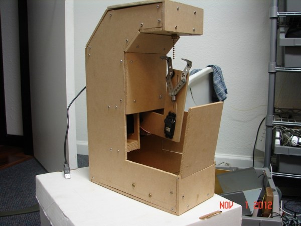
The mechanical simplicity of this pull-string controlled most useless machine is delightful. You can see the metal gripper which is reaching up to tug on a light-fixture-style pull chain. This is how it turns itself off after you’ve pulled the string to power it up.

The device is [Alex555’s] entry in the 7400 Logic competition. We do hope that he ends up posting a schematic because we’d love to see the gritty details of how it works. After the break you can watch two doors open, allowing the arm to raise up and the gripper to grab the chain. This takes just four servo motors, which are controlled by the signal from a 555 timer and some accompanying hardware.

Apparently the chain is a fake, as the servos didn’t provide enough force to actuate that type of switch. It’s not a surprise as those pull chains do require quite a tug. An optical sensor was used to trigger the movement when your hand reaches for the chain.

Continue reading “Pull-string Most Useless Machine”

ATmega1284 As An 8-voice 32 KHz Synthesizer

A couple of things strike us about this 8-voice 32 kHz synthesizer. First is the cleanliness of the prototype. As you can see, each part has plenty of room on its own board and all are interconnected by 10-pin IDC ribbon connectors. But you’ll have to see the video after the break to enjoy the impressive sound that this puts out. You’ll hear it play the Super Mario Bros. theme; it does it with passion!

To get audio from the digital microcontroller [Mike] built his own R2R digital to analog converter. The resistor ladder is built from sixteen resistors, which feed a rail-to-rail amplifier. The sound is mono but the playback is polyphonic thanks to the work done by the ATmega1284. It is reading MIDI commands coming in from an external controller (we assume it’s the computer on which the hardware is sitting). The chip’s 128 KB of Flash memory leave plenty of room to store samples, which are selected from a lookup table based on the MIDI data. If more than one sample is to be played the chip averages the data and sets the 8-bit output port accordingly.

Continue reading “ATmega1284 As An 8-voice 32 KHz Synthesizer”

Building A 100 MHz Frequency Counter

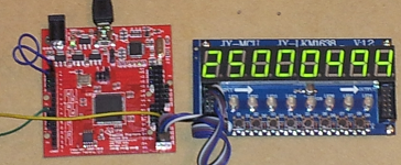
The great thing about building with gates is the crazy speeds you can achieve by using hardware directly (as opposed to working with simple microcontrollers). This 100 MHz frequency counter is a great example. [Michael] just finished building it using a Papilio board.

Of course we’re not talking about discreet chips here. The Papilio is an FPGA development board which means he is building with hardware gates, but that is still done by writing code. Above, the rig is measuring a 25 MHz being generated by a second FPGA board. Using the Papilio’s on board 32 MHz clock the device is capable of counting a frequency up to 100 MHz. You can see it measuring a 96.875  MHz signal in the video after the break. One interesting thing about that clip is that near the end he touches the crystal’s case with his finger and the Hertz really jump for a moment.

If the 8-digit display looks familiar that’s because [Michael] recently published a library to use it with an FPGA.

Continue reading “Building A 100 MHz Frequency Counter”

Laptop Motherboard Reborn As A Low-wattage Server

[Darknezz] sent us a set of photos and some details about his damaged laptop motherboard turned into a server. A client brought him a Dell 1525 on which nothing was showing up on the LCD screen. The HDMI and VGA still worked, and he traced the problem to no signal coming out of the motherboard. He swapped the board out to get the laptop working again, but he client said he could keep the damaged one.

It has a dual-core CPU which meets his needs and since it’s meant to run off of a battery it’s as energy-efficient as possible. [Darknezz] dug through his parts bin and found a PSU that could supply the needed 19.5V at 3.5A. The connector didn’t match but it didn’t take him too long to patch into it using a spare Molex connector. He also needed a power button and ended up soldering a momentary push switch to a couple of pads which he traced out form the original connector. The only thing he actually ended up purchasing were the memory modules. Check out the photos he took of the alterations in the gallery after the break.

Continue reading “Laptop Motherboard Reborn As A Low-wattage Server”

How Computers Work, Starting With Transistor Gates

[Andrew Gibiansky] has just started a tutorial series called Computing with Transistors. It’s purpose is to pull back the many veiled layers between high level languages and the controlling of electrons. And fittingly this first post starts off by explaining voltage source, load, and current. Don’t be thrown by its simplicity though. [Andrew] quickly moves on to talk about switching transistors and how they are used to build gates like the OR NOR gate seen above.

If this is the least bit interesting you should also look back at the post about Nand 2 Tetris. It’s an online course that works its way through The Elements of Computing Systems text book. We’ve been following that journey ourselves, having made it through the hardware build in about a week. The assembler took about the same amount of time, and right now we’re in debugging hell trying to get the last function call and return parts of the VM translator to work right. We’ve used most of the skills needed in this journey before, but never all in one project. It really has shed a lot of light on the gaps in our knowledge, and we’re having a lot of fun at the same time!

[via Reddit]

BeagleBone Powers This Networked LED Marquee

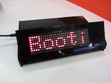
[Mahmut] calls this project SmartBox. It’s a BeagleBone controlled LED marquee which can pull down information off of the Internet.

The project started with the display itself. [Mahmut] used six 5×7 LED modules to populate a circuit board he produced himself. The low side of the modules is controlled by some MBI5026 constant current drivers, with PNP transistors on the high side. The display connects to the BeagleBone ARM board using a couple of IDC ribbon cable connectors. With that up and running he started working on the enclosure. The display board was modeled in Google SketchUp to ensure that the case design would fit it properly. The laser cut acrylic case is in two parts, the base holds the driver electronics, with a hinged section for adjusting the angle of the marquee.

So far there are a few different connectivity features which are shown off in the clip after the break. The BeagleBone has the ability to pull down Twitter feeds, notify about incoming email, and scroll messages.

Continue reading “BeagleBone Powers This Networked LED Marquee”