Hackaday Prize Entry: MyComm Handheld Satellite Messenger

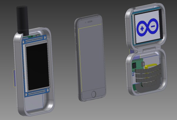
We live in a connected world, but that world ends not far beyond the outermost cell phone tower. [John Grant] wants to be connected everywhere, even in regions where no mobile network is available, so he is building a solar powered, handheld satellite messenger: The MyComm – his entry for the Hackaday Prize.

The MyComm is a handheld touch-screen device, much like a smartphone, that connects to the Iridium satellite network to send and receive text messages. At the heart of his build, [John] uses a RockBLOCK Mk2 Iridium SatComm Module hooked up to a Teensy 3.1. The firmware is built upon a FreeRTOS port for proper task management. Project contributor [Jack] crafted an intuitive GUI that includes an on-screen keyboard to write, send and receive messages. A micro SD card stores all messages and contact list entries. Eventually, the system will be equipped with a solar cell, charging regulator and LiPo battery for worldwide, unconditional connectivity.

2016 will be an interesting year for the Iridium network since the first satellites for the improved (and backward-compatible) “Iridium NEXT” network are expected to launch soon. At times the 66 Iridium satellites currently covering the entire globe were considered a $5B heap of space junk due to deficiencies in reliability and security. Yet, it’s still there, with maker-friendly modems being available at $250 and pay-per-use rates of about 7 ct/kB (free downstream for SDR-Hackers). Enjoy the video of [Jack] explaining the MyComm user interface:

Continue reading “Hackaday Prize Entry: MyComm Handheld Satellite Messenger”

EV History: The Lightning Precedes The Thunder

In 1988, a bunch of engineers from Hotzenwald, Germany, came together and decided that it is time for the future of mobility: A new, more modern and environmentally friendly car should put an end to fossils and emissions while still being fun to drive. “It should become a new kind of car. Smaller, lighter, cleaner – and more beautiful” is how future CEO Thomas Albiez described his mission. For the first time in automotive history, this series car would be designed as an all-electric vehicle from the start and set a new standard for mobility. The project was given the codename “Hotzenblitz” (“Hotzen Bolt”) to indicate how the idea came to them: Like a lightning bolt. The snarky regional term also came with a double meaning: Imaginary lightning bolts, used for insurance fraud.

hotzenblitz_chassis
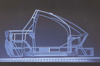
Hotzenblitz frame construction (origin unknown, image source)

Unnoticed by the rest of the world, they founded Hotzenblitz Mobile. Industrial Designer Harold Schurz was contracted to design the chassis for the Hotzenblitz, which was then modeled into a prototype chassis. The self-funded team moved fast. An external motorsports company helped to develop the tubular steel frame, and soon their vision took on shape. After the team had fitted a motor and transmission into the frame, CEO Thomas Albiez himself installed the traction battery and drive train. The team felt confident with the result, and in July 1990, during an open house day in the office, they somewhat spontaneously decided to call Green Tech entrepreneur and chocolate mogul Alfred Ritter.

Alfred Ritter had experienced financial losses after the Chernobyl Disaster. Many agricultural regions, including several hazelnut plantations that were vital to Alfred’s chocolate business, were irreversibly lost to the fallout contamination. It was then when he turned to the green energy business, founding the Paradigma group to manufacture solar collector systems and pellet heaters. When Thomas and the team called, Alfred jumped on the idea of an electric car. In the same year, Alfred Ritter and his sister Marli Hoppe-Ritter became shareholders in the company and helped to finance the future of the Hotzenblitz.

Continue reading “EV History: The Lightning Precedes The Thunder”

Hackaday Prize Entry: DIY Automatic Tool Changer

Choosing between manually changing endmill bits on a CNC machine and investing in an expensive automated solution? Not for [Frank Herrmann], who invented the XATC, an eXtremely simple Automated Tool Changer. [Frank’s] ingenious hack achieves the same functionality as an industrial tool changer using only cheap standard hardware you might have lying around the workshop.

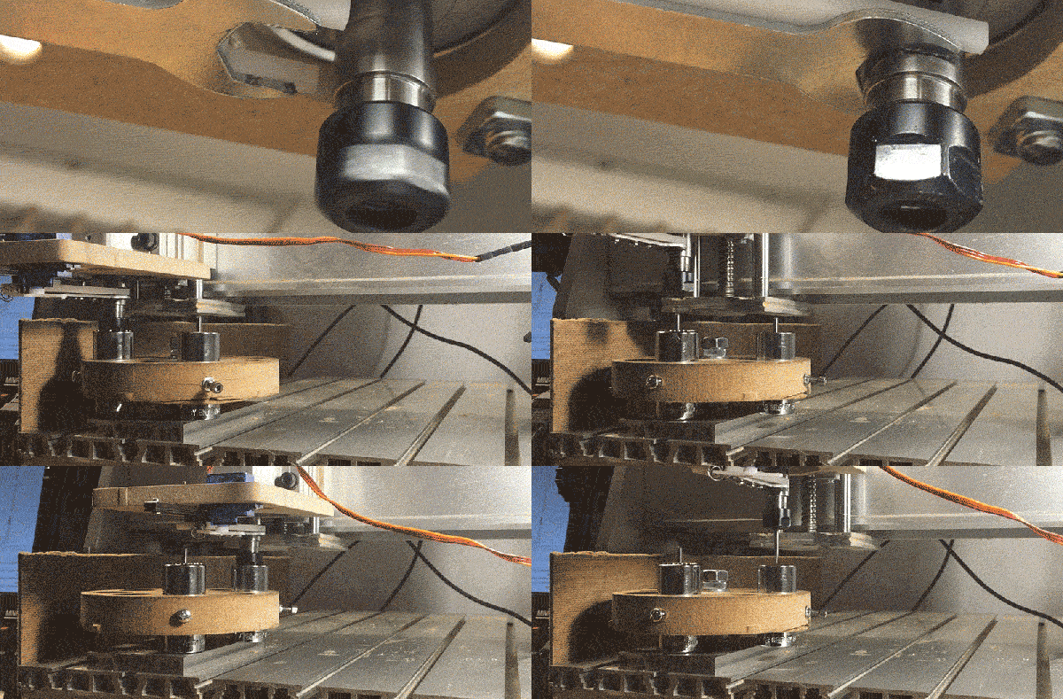
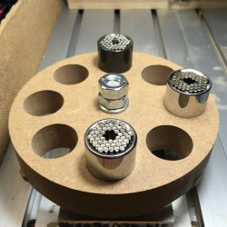
xatc_carouselLike many ATCs, this one features a tool carousel. The carousel, which is not motorized, stores each milling bit in the center bore of a Gator Grip wrench tool. To change a tool, a fork wrench, actuated by an RC servo, blocks the spindle shaft, just like you would do it to manually change a tool. The machine then positions the current bit in an empty Gator Grip on the carousel and loosens the collet by performing a circular “magic move” around the carousel. This move utilizes the carousel as a wrench to unscrew the collet. A short reverse spin of the spindle takes care of the rest. It then picks another tool from the carousel and does the whole trick in reverse.

The servo is controlled via a WiFi connected NodeMCU board, which accepts commands from his CNC controller over HTTP. The custom tool change sequences are provided by a few JavaScript macros written for the TinyG workspace on chilipeppr.com, a browser-based G-code host. Enjoy the video of [Frank Herrmann] explaining his build!

Thanks to Smoothieboard creator [Arthur Wolf], who is currently working on a similar project, for the tip!

The HackadayPrize2016 is Sponsored by:

How Lasers Actually Work

Lasers are optical amplifiers, optical oscillators, and in a way, the most sophisticated light source ever invented. Not only are lasers extremely useful, but they are also champions of magnitude: While different laser types cover the electromagnetic spectrum from radiation (<10 nm) over the visible spectrum to far infrared light (699 μm), their individual output band can be as narrow as a few µHz. Their high temporal and spatial coherence lets them cover hundreds of meters in a tight beam of lowest divergence as a perfectly sinusoidal, electromagnetic wave. Some lasers reach peak power outputs of several exawatts, while their beams can be focused down to the smallest spot sizes in the hundreds and even tens of nanometers. Laser is the acronym for Light Amplification by Stimulated Emission Of Radiation, which suggests that it makes use of a phenomenon called stimulated emission, but well, how exactly do they do that? It’s time to look the laser in the eye (Disclaimer: don’t!).

Continue reading “How Lasers Actually Work”

Soldering Challenge To Challenge You

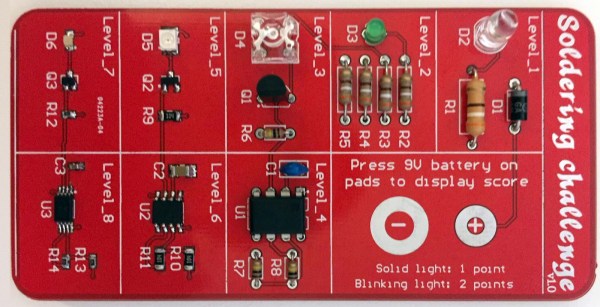
[Rick] knew that the blinking, beeping microcontroller kits that are commonly used for educational soldering workshops just would not cut it for a serious combat among SMD reworking professionals. The “Soldering Challenge” he created to fill this gap is a little PCB with eight difficulty levels from large through hole components to the smallest hand solderable SMDs. After assembly, the circuit assesses the skill level of the soldering aspirant based on a built-in scoring system.

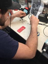
soldering_challenge_ongoingThe challenge is meant to be played on a time limit. There are no two same-sized components of different value, so contestants may focus on soldering fast. Little rubber pads on the backside of the board provide for good ground contact in the curves. After the starting signal, you will be confronted with a few through hole resistors, a capacitor, different LEDs and a DIP-8 IC. Here it’s all about the speed and efficiency as you tackle a track full of bends and cut-off resistor legs. Over the course of the challenge, the components get smaller and smaller, until you finally reach the 0603 level, with a tiny SC-85 MOS-FET and a TSSOP 555 timer at the finishing line.
Continue reading “Soldering Challenge To Challenge You”

How To Set Up And Run A Makerspace

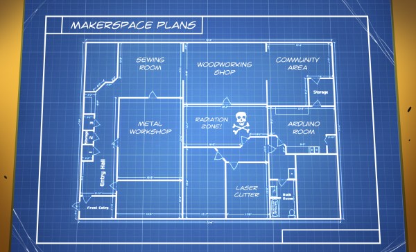
A bunch of people who share a large workshop and meet on a regular basis to do projects and get some input. A place where kids can learn to build robots instead of becoming robots. A little community-driven factory, or just a lair for hackers. The world needs more of these spaces, and every hackerspace, makerspace or fab lab has its very own way of making it work. Nevertheless, when and if problems and challenges show up – they are always the same – almost stereotypically, so avoid some of the pitfalls and make use of the learnings from almost a decade of makerspacing to get it just right. Let’s take a look at just what it takes to get one of these spaces up and running well.

Continue reading “How To Set Up And Run A Makerspace”

Hackaday Prize Entry: Micro Robots For Education

[Joshua Elsdon] and [Thomas Branch] needed a educational hardware platform that would fit into the constrained spaces and budgets of college classes. Because nothing out there that was cheap, simple and capable enough to fit their program, the two teachers for robotics at the Imperial College Robotics Society set out to build their own – and entered the Hackaday Prize with a legion of open source Micro Robots.

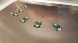
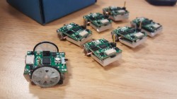
These small robots have a base area of 2 cmand a price tag of about £10 (about $14) each, once they are produced in quantities. They feature two onboard stepper motors, an RGB-LED, battery, a line-following sensor, collision-sensors and a bidirectional infrared transmitter for communicating with a master system, the ‘god bot’. The master system is based on a Raspberry Pi with little additional hardware. It multiplexes the IR-communication with all the little robots and simultaneously tracks their position and orientation through a camera, identifying them via their colored onboard LED. The master system also provides a programming interface for the robots, so that no firmware flashing procedure is required for students to get their code running. This is a well-designed, low-cost multi-robot system, and with onboard sensors, stepper motor odometry, and absolute positioning feedback, these little robots can be taught quite a few tricks.

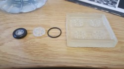
Building tiny robots comes with a lot of regular-sized challenges, and we’re delighted to follow [Joshua Elsdon] and [Thomas Branch] on their journey from assembling the tiny PCBs over experimenting with 3D printing and casting techniques to produce the tiny wheels to the ROS programming. The diligent duo is present in the Hackaday prize twice: With their own Micro Robots project and with their contribution to the previously covered ODrive – an open source BLDC servo controller. We are already curious about their next feat! The below video shows a successful test of the camera feedback integration into the ROS.

The HackadayPrize2016 is Sponsored by: