Modular robot legs from Disney

Disney’s New Robot Limbs Trained Using Neural Networks

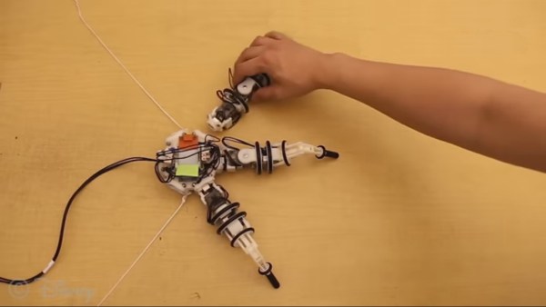
Disney is working on modular, intelligent robot limbs that snap into place with magnets. The intelligence comes from a reasonable sized neural network that also incorporates some modularity. The robot is their Snapbot whose base unit can fit up to eight of limbs, and so far they’ve trained with up to three together.

The modularity further extends to a choice of three types of limb. One with roll and pitch, another with yaw and pitch, and a third with roll, yaw, and pitch. Interestingly, of the three types, the yaw-pitch one seems most effective.

Learning environment for Disney's modular robot legs
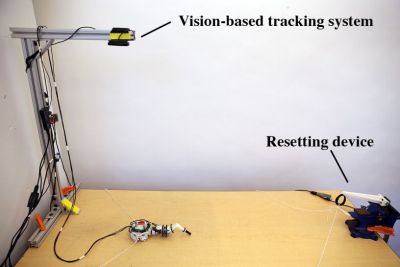
In this age of massive, deep neural networks requiring GPUs or even online services for training in a reasonable amount of time, it’s refreshing to see that this one’s only two layers deep and can be trained in three hours on a single-core, 3.4 GHz Intel i7 processor. Three hours may still seem long, but remember, this isn’t a simulation in a silicon virtual world. This is real-life where the servo motors have to actually move. Of course, they didn’t want to sit around and reset it after each attempt to move across the table so they built in an automatic mechanism to pull the robot back to the starting position before trying to cross the table again. To further speed training, they found that once they’d trained for one limb, they could then copy the last of the network’s layers to get a head starting on the training for two limbs.

Why do training? Afterall, we’ve seen pretty awesome multi-limbed robots working with manual coding, an example being this hexapod tank based on one from the movie Ghost in the Shell. They did that too and then compared the results of the manual approach with those of the trained one and the trained one moved further in the same amount of time. At a minimum, we can learn a trick or two from this modular crawler.

Check out their article for the details and watch it in action in its learning environment below.

Continue reading “Disney’s New Robot Limbs Trained Using Neural Networks”

Using AI to see through walls

Using An AI And WiFi To See Through Walls

It’s now possible to not only see people through walls but to see how they’re moving and if they’re walking, to tell who they are. We finally have the body scanner which Schwarzenegger walked behind in the original Total Recall movie.

Seeing through walls: real life, poses, skeletons
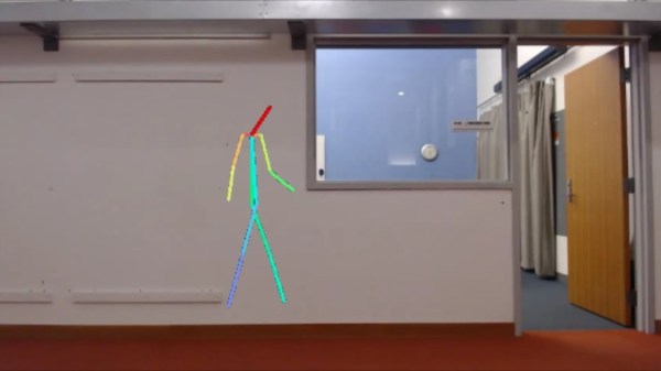
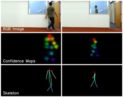
This is the work of a group at the MIT Computer Science and Artificial Intelligence Laboratory (CSAIL). The seeing-through-the-wall part is done using an RF transmitter and receiving antennas, which isn’t very new. Our own [Gregory L. Charvat] built an impressive phased array radar in his garage which clearly showed movement of complex shapes behind a wall. What is new is the use of neural networks to better decipher what’s received on those antennas. The neural networks spit out pose estimations of where people’s heads, shoulders, elbows, and other body parts are, and a little further processing turns that into skeletal figures.

They evaluated its accuracy in a number of ways, all of which are detailed in their paper. The most interesting, or perhaps scariest way was to see if it could tell who the skeletal figures were by using the fact that each person walks with their own style. They first trained another neural network to recognize the styles of different people. They then pass the pose estimation output to this style-recognizing neural network and it correctly guessed the people with 83% accuracy both when they were visible and when they were behind walls. This means they not only have a good idea of what a person is doing, but also of who the person is.

Check out the video below to see some pretty impressive side-by-side comparisons of live action and skeletal versions doing all sorts of things under various conditions. It looks like the science fiction future in Total Recall has gotten one step closer. Now if we could just colonize Mars.

Continue reading “Using An AI And WiFi To See Through Walls”

Wireless SMD microscope ring light

Wireless Ring Light For SMD Microscope

When [Felix Rusu], maker of the popular Moteino boards which started life as wireless Arduino compatibles, says he’s made a wireless ring light for his SMD microscope, we redirect our keystrokes to have a look. Of course, it’s a bit of wordplay on his part. What he’s done is made a new ring light which uses a battery instead of having annoying wires go to a wall wart. That’s important for someone who spends so much time hunched over the microscope. Oh, and he’s built the ring light on a rather nice looking SMD board.

The board offers a few power configurations. Normally he powers it from a 1650 mAh LiPo battery attached to the rear of his microscope. The battery can be charged using USB or through a DC jack for which there’s a place on the board, though he hasn’t soldered one on yet. In a pinch, he can instead power the light from the USB or the DC jack, but so far he’s getting over 6 hours on a single charge, good enough for an SMD session.

The video below shows his SMD board manufacturing process, from drawing up the board in Eagle, laser cutting holes for a stencil, pasting, populating the board, and doing the reflow, along with all sorts of tips along the way. Check it out, it makes for enjoyable viewing.

Here’s another microscope ring light with selectable lighting patterns for getting rid of those pesky shadows. What features would make your SMD sessions go a little easier?

Continue reading “Wireless Ring Light For SMD Microscope”

Smelting aluminum in a microwave oven

A Different Use For Microwave Oven: Melting Aluminum

Microwave ovens are a treasure trove of useful parts: transformers, an HV capacitor, a piezo speaker, and a high torque motor, to name just a few. In a new twist, [Rulof Maker] strips all that out and uses just the metal case to make a furnace for melting aluminum, copper and bronze.

His heat source is a quartet of 110 volt, 450 watt quartz heating elements which he mounts inside in the back. To reduce heat loss, he lines the walls with ceramic fiber insulation. Unfortunately, that includes covering the inside of the window, so there’s no pressing your nose against the glass while you watch the aluminum pieces turn to liquid. If you’re going to try making one of these yourself then you may want to consider adding a fuse.

It does the job though. In around nine minutes he melts enough scrap aluminum in a stainless steel bowl to pour into a mold for a test piece. But don’t take our word for it, see for yourself in the video below.

If want more information on what useful parts are inside then check out this primer. Or you can leave the parts in and use the oven as is for melting lead, but keep a fire extinguisher handy.

Continue reading “A Different Use For Microwave Oven: Melting Aluminum”

TL084 die blocks

Ken Shirriff Found Butterflies In His Op-Amp

In 1976, Texas Instruments came out with the TL084, a four JFET op-amp IC each with similar circuitry to Fairchild’s very popular single op-amp 741. But even though the 741 has been covered in detailed, when [Ken Shirriff] focused his microscope on a TL084, he found some very interesting things.

JFETs on the TL084 op-amp

To avoid using acid to get at the die, he instead found a ceramic packaged TL084 and pried off the cover. The first things he saw were four stabilizing capacitors, by far the largest structures on the die and visible to the naked eye.

When he peered into his microscope he next saw butterfly shapes which turned out to be pairs of input JFETs. The wide strips are the gates and the narrower strip surrounded by each gate is the source. The drain is the narrow strip surrounding each gate. Why arrange four JFETs like this? It’s possible to have temperature gradients in the IC, one side being hotter than the other. These gradients can affect the JFET’s characteristics, unbalancing the inputs. Look closely at the way the JFETs are connected and you’ll see that the top-left one is connected to the bottom-right one, and similarly for the other two. This diagonal cross-connecting cancels out any negative effects.

[Ken’s] analysis in his article doesn’t stop there though. Not only does he talk more about these JFETs but he goes over the rest of the die too. It’s well worth the read, as is his write-up about the 741 which we’ve also covered.

James Bruton's mini electric bike

Building A Mini Electric Bike In Between Projects

What do you do when you suddenly find you have some free time because you’re waiting on parts or have run up against other delays for your current project? If you’re [James Bruton], you design and build a mini electric bike.

Being a prolific builder, [James] already had the parts he needed. Some of them were left over from previous projects: a small motor, a 24 volt LiPo battery, an SK8 electronic speed controller, and a twist grip for the handlebars. He cut a wooden frame using his CNC machine and 3D printed various other components. Normally he uses ABS for motor mounts but this time he went with PLA and sure enough, the motor heated up and the mounting screws got hot enough to melt the plastic. But other than that, the bike worked great and looks like a polished, manufactured product. How many of us can say the same for our own unplanned projects using only parts from around the workshop? Check out his build and watch him whizzing around on it in the video below.

As for the former projects from which he had leftover parts, he says that some came from skateboard projects such as his pimped out electric LEGO longboard.

Continue reading “Building A Mini Electric Bike In Between Projects”

MakerbotCNC PCB etcher

Makerbot Printer Reborn As PCB Engraver

Makerbot 3D printers were among the first to hit the market, so it makes sense that old and broken ones now litter the shelves of hackerspaces and home workshops alike. Rather than throw his one out, [Foaly] saw an opportunity to convert it to some sort of CNC machine. Given its lack of inherent rigidity and relatively weak motors, he opted to make a low-impact circuit board engraver which he appropriately calls the MakerbotCNC. We like the thought he put into this project, and it was clearly backed by plenty of experience.

Circuit board etched using MakerbotCNC

Fortunately, his Makerbot Replicator 2 stemmed from a time when MakerBot was more open, meaning he could control the machine using a simple, open library. A little more open software handled his conversion of Gerber files to G-code. First tests drawing with a pen were successful, so he moved on to the carving head. He opted for an inrunner brushless motor to minimize dust getting into the motor but since these motors have a tendency to heat up he had to add fans to cool it. That still didn’t stop the heat from melting and bending his attempt at a 3D printed PLA carriage, so he switched it to a laser-cut MDF board to fix it. Finding the right collet proved tricky but eventually, he found the perfect fit was a collet clutch normally used to couple flex shafts to RC boat motors.

The result, as you can see was worth it. Using shallow passes, he can even cut carbon fiber parts.

While [Foaly] didn’t opt to replace more parts and go for a more powerful CNC, check out this 3D printer to CNC conversion which can cut wood, acrylic, and even aluminum.