History Of The Capacitor – The Modern Era

The pioneering years in the history of capacitors was a time when capacitors were used primarily for gaining an early understanding of electricity, predating the discovery even of the electron. It was also a time for doing parlor demonstrations, such as having a line of people holding hands and discharging a capacitor through them. The modern era of capacitors begins in the late 1800s with the dawning of the age of the practical application of electricity, requiring reliable capacitors with specific properties.
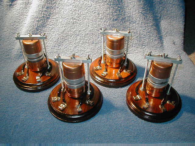
Leyden Jars

Marconi with transmitting apparatus
Marconi with transmitting apparatus, Published on LIFE [Public domain], via Wikimedia Commons
One such practical use was in Marconi’s wireless spark-gap transmitters starting just before 1900 and into the first and second decade. The transmitters built up a high voltage for discharging across a spark gap and so used porcelain capacitors to withstand that voltage. High frequency was also required. These were basically Leyden jars and to get the required capacitances took a lot of space.

Mica

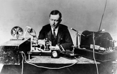
In 1909, William Dubilier invented smaller mica capacitors which were then used on the receiving side for the resonant circuits in wireless hardware.

Early mica capacitors were basically layers of mica and copper foils clamped together as what were called “clamped mica capacitors”. These capacitors weren’t very reliable though. Being just mica sheets pressed against metal foils, there were air gaps between the mica and foils. Those gap allowed for oxidation and corrosion, and meant that the distance between plates was subject to change, altering the capacitance.

In the 1920s silver mica capacitors were developed, ones where the mica is coated on both sides with the metal, eliminating the air gaps. With a thin metal coating instead of thicker foils, the capacitors could also be made smaller. These were very reliable. Of course we didn’t stop there. The modern era of capacitors has been marked by one breakthrough after another for a fascinating story. Let’s take a look.

Continue reading “History Of The Capacitor – The Modern Era”

Books You Should Read: Instruments Of Amplification

Psst… Wanna make a canning jar diode? A tennis ball triode? How about a semiconductor transistor? Or do you just enjoy sitting back and following along an interesting narrative of something being made, while picking up a wealth of background, tips and sparking all sorts of ideas? In my case I wanted to make a cuprous oxide semiconductor diode and that lead me to H.P. Friedrichs’ wonderful book Instruments of Amplification. It includes such a huge collection of amplifier knowledge and is a delight to read thanks to a narrative style and frequent hands-on experiments.

Friedrichs first authored another very popular book, The Voice of the Crystal, about making crystal radios, and wanted to write a second one. For those not familiar with crystal radios, they’re fun to make radios that are powered solely by the incoming radio waves; there are no batteries. But that also means the volume is low.

Readers of that book suggested a good follow-up would be one about amplifier circuits, to amplify the crystal radio’s volume. However, there were already an abundance of such books. Friedrichs realized the best follow-up would be one on how to make the amplifying components from scratch, the “instruments of amplification”.  It would be unique and in the made-from-scratch spirit of crystal radios. The book, Instruments of Amplification was born.

The Experiments

Microphonic relays
Microphonic relays, via H.P. Friedrichs Homepage

The book includes just the right amount of a history, giving background on what an amplifier is and how they first came in the electrical world. Telegraph operators wanted to send signals over greater and greater distances and the solution was to use the mix of electronics and mechanics found in the telegraph relay. This is the springboard for his first project and narrative: the microphonic relay.

The microphonic relay example shown on the right places a speaker facing a microphone; the speaker is the input with the microphone amplifying the output. He uses a carbon microphone salvaged from an old telephone headset, housing everything in an enclosure of copper pipe caps, steel bar stock, nuts and bolts mounted on an elegant looking wood base. All the projects are made with simple parts, with care, and they end up looking great.

Continue reading “Books You Should Read: Instruments Of Amplification”

Red Carpet BB-8 internals

How BB-8 Works Revealed At Star Wars Celebration Europe

Finally the workings of the official BB-8 that you’ve seen rolling around at various events have been revealed. Its makers [Matt Denton] and [Josh Lee] participated in an hour-long presentation at Star Wars Celebration Europe 2016 just this past week where the various views of its internals were shown in action. It’s since had BB-8 builders (yours truly included) analyzing the workings for new ideas. We also now have the official name for it, red carpet BB-8.

For the first half of their talk they went over how BB-8 was implemented for Star Wars: The Force Awakens. As we’ve long known this was done using 7 puppeted BB-8’s, though it was revealed that only 4 were actually used, including a stationary one called the wiggler whose purpose you can guess. Another thing we didn’t know is that they did consider building a working BB-8 for filming but decided they needed something bullet proof, that would work right every time without making a film crew wait for repairs, and so went with the puppets instead.

The second half of their talk contained the big reveal, the mechanism inside red carpet BB-8’s ball. It turns out to be pretty close to what many builders have been doing. If you’ve seen the DIYer’s guide to the different BB-8 drive systems then you’ll understand when we say it’s a pendulum drive (aka axle drive). That is, there’s a motorized axle that crosses the middle of the ball and the ball rotates on that axle. Meanwhile a large mass suspended below the axle acts as the pendulum mass.

BB-8 builders have known the importance of keeping as much mass as possible as low down as possible for stability, but it was revealed the great extent to which that has been done in the red carpet version. Motors for the head’s pitch and yaw are located at the bottom and their motion is transferred up to the center using what are maybe best known as bicycle brake cables. Another big reveal was a linear actuator for the body roll, tilting the center stuff with respect to the mass lower down. The actuator itself is located in the lower section. Also, BB-8 builders have been mounting the drive motors for rotating the ball with respect to the axle, in line with the axle. However, in red carpet BB-8 the motor is also at the bottom and its motion appears to be transferred up to the axle via belt and worm gears. You may mistake the gold cylinders on either side of the central gimbal system to be motors but they’re actually Moflon slip rings.

Those are just a few of the insights gained so far from analyzing the video below. Doubtless people will be noticing a lot more in the weeks to come.

Continue reading “How BB-8 Works Revealed At Star Wars Celebration Europe”

LEGO Monowheel Corners Like It’s On Rails

[Jason]’s at it again. This time the LEGO maestro is working on a LEGO BB-8 droid. As a first step he’s made a motorized monowheel that not only races along hallways and through living rooms at the peril of any passing people, but turns as well.

To drive it forward there’s an axle that runs across the center of the wheel and a motor that rotates that axle. He’s also included some weight bricks. Without the mass of those bricks for the rotation to work against, the motor and axle would just spin in place while the friction of the floor keeps the wheel from rotating. If you’ve seen the DIYer’s guide to making BB-8 drive systems, you’ll know that this is classified as an axle drive system.

LEGO monowheel interior shown while leaning to turn

For steering the monowheel left or right he has another mass located just above the axle. Shifting the mass to the left causes the monowheel to lean and move in that direction. Shifting the mass to the right makes the wheel move to the right in the same fashion. Being ever efficient, [Jason] has the motor that shifts the mass doubling as the mass itself.

As with any proof-of-concept, there are still some issues to work out. When turning the wheel left or right it can tip onto its side. Ridges on both sides of the wheel’s circumference reduce the chances of that happening but don’t eliminate it altogether. Also, the steering mass/motor doesn’t yet have a self-centering mechanism; after a turn it’s up to the person holding the remote control to find center. If the mass isn’t correctly centered after a turn, there tends to be some wobble.

As always, we’re looking forward to seeing how [Jason] solves those issues but first he’ll have to put it back together since, as you can see from the video below, it didn’t quite pass the stair test.

Continue reading “LEGO Monowheel Corners Like It’s On Rails”

Marc with cannula and brain monitor

In Bed With An Arduino, Fighting Sleep Apnea

Sometimes the journey is as interesting as the destination, and that’s certainly the case with [Marc]’s pursuit of measuring his sleep apnea (PDF, talk slides. Video embedded below.). Sleep apnea involves periods of time when you don’t breathe or breathe shallowly for as long as a few minutes and affects 5-10% of middle-aged men (half that for women.) [Marc]’s efforts are still a work-in-progress but along the way he’s tried a multitude of things, all involving different technology and bugs to work out. It’s surprising how many ways there are to monitor breathing.

Debugging the Eeonyx conductive fabric approach

His attempts started out using a MobSenDat Kit, which includes an Arduino compatible board, and an accelerometer to see just what his sleeping positions were. That was followed by measuring blood O2 saturation using a cheap SPO2 sensor that didn’t work out, and one with Bluetooth that did work but gave results as a graph and not raw data.

Next came measuring breathing by detecting airflow from his nose using a Wind Sensor, but the tubes for getting the “wind” from his nose to the sensor were problematic, though the approach was workable. In parallel with the Wind Sensor he also tried the Zeo bedside sleep manager which involves wearing a headband that uses electrical signals from your brain to tell you what sleep state you’re in. He particularly liked this one as it gave access to the data and even offered some code.

And his last approach we know of was to monitor breathing by putting some form of band around his chest/belly to measure expansion and contraction. He tried a few bands and an Eeonyx conductive textile/yarn turned out to be the best. He did run into noise issues with the Xbee, as well as voltage regulator problems, and a diode that had to be bypassed.

But while [Marc]’s list of approaches to monitor sleep is long, he hasn’t exhausted all approaches. For example there’s monitoring a baby using lasers to detect whether or not the child is still breathing.

Continue reading “In Bed With An Arduino, Fighting Sleep Apnea”

Expanding Horizons With The Ion Propelled Lifter

Like many people, going through university followed an intense career building period was a dry spell in terms of making things. Of course things settled down and I finally broke that dry spell to work on what I called “non-conventional propulsion”.

I wanted to stay away from the term “anti-gravity” because I was enough of a science nut to know that such a thing was dubious. But I also suspected that there might be science principles yet to be discovered. I was willing to give it a try anyway, and did for a few years. It was also my introduction to the world of high voltage… DC. Everything came out null though, meaning that any effects could be accounted for by some form of ionization or Coulomb force. At no time did I get anything to actually fly, though there was a lot of spinning things on rotors or weight changes on scales and balances due to ion propulsion.

So when a video appeared in 2001 from a small company called Transdimensional Technologies of a triangle shaped, aluminum foil and wire thing called a lifter that actually propelled itself off the table, I immediately had to make one. I’d had enough background by then to be confident that it was flying using ion propulsion. And in fact, given my background I was able to put an enhancement in my first version that others came up with only later.

For those who’ve never seen a lifter, it’s extremely simple. Think of it as a very leaky capacitor. One electrode is an aluminum foil skirt, in the shape of a triangle. Spaced apart from that around an inch or so away, usually using 1/6″ balsa wood sticks, is a very thin bare wire (think 30AWG) also shaped as a triangle. High voltage is applied between the foil skirt and the wire. The result is that a downward jet of air is created around and through the middle of the triangle and the lifter flies up off the table. But that is just the barest explanation of how it works. We must go deeper!

Continue reading “Expanding Horizons With The Ion Propelled Lifter”

History Of The Capacitor – The Pioneering Years

The history of capacitors starts in the pioneering days of electricity. I liken it to the pioneering days of aviation when you made your own planes out of wood and canvas and struggled to leap into the air, not understanding enough about aerodynamics to know how to stay there. Electricity had a similar period. At the time of the discovery of the capacitor our understanding was so primitive that electricity was thought to be a fluid and that it came in two forms, vitreous electricity and resinous electricity. As you’ll see below, it was during the capacitor’s early years that all this changed.

The history starts in 1745. At the time, one way of generating electricity was to use a friction machine. This consisted of a glass globe rotated at a few hundred RPM while you stroked it with the palms of your hands. This generated electricity on the glass which could then be discharged. Today we call the effect taking place the triboelectric effect, which you can see demonstrated here powering an LCD screen.

Continue reading “History Of The Capacitor – The Pioneering Years”