Put An ItsyBitsy Zork In Your Pocket

Before computer games had all these fancy graphics, text based games were a very popular genre. Rather than move a character on the screen, you’d type out commands for your player in sentence form which the game would interpret; decades before the “cloud” language processing technology that the likes of Amazon and Google currently use to power their virtual assistants. In some ways the genre was ahead of its time, but it didn’t survive the graphical revolution for home computers. Of course, these games still have some diehard fans out there.

[Dan The Geek] is one such fan. He loves text based adventure games like Zork so much that he wanted to create his own implementation of the core technology that made these games possible all those years ago. But he didn’t want to just do it on this desktop computer, there’s already projects that let you run these classic games on modern hardware. He wanted to see if he could run these classic games on a modern microcontroller, and create a authentic retro experience on a handy portable device.

[Dan] starts by explaining the technology used to make titles like these possible in the days when the wide array of home computer types required a nuanced approach. By separating the story files from the actual interpreter, developers could more easily port the games to various computers. In theory these interpreters, known as “Z-machines”, could be written for any computer that could compile C code, had enough RAM to hold the story, and had a terminal and keyboard. Not exactly the kind of system requirements we’re used to seeing for modern PC games, but it was the 1980’s.

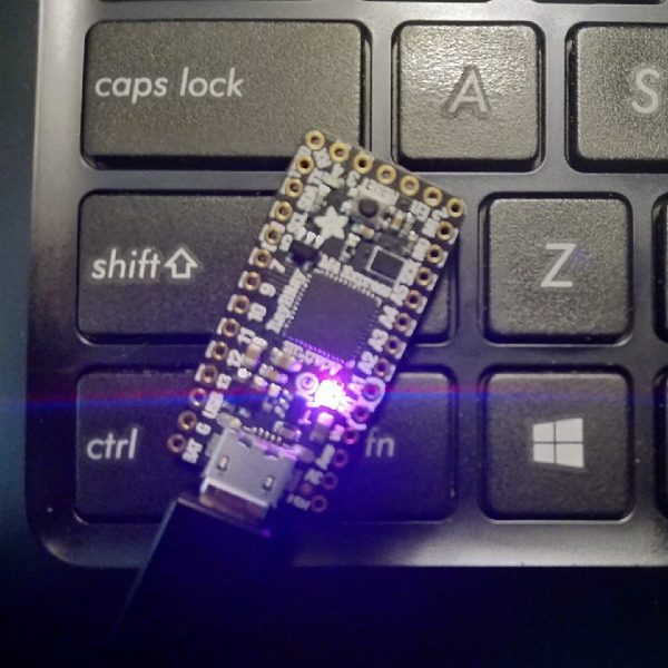
In theory a modern microcontroller will meet these requirements, so [Dan] wanted to create his own Z-machine for one. But rather than “cheat” by using an SD card like previous Arduino Z-machines have, he wanted to see if there was a development board out there that could do it all internally. The answer came in the form of the  Adafruit ItsyBitsy M4 Express, with its 192 kB of RAM and 2 MB of SPI flash.

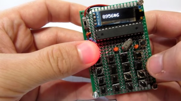
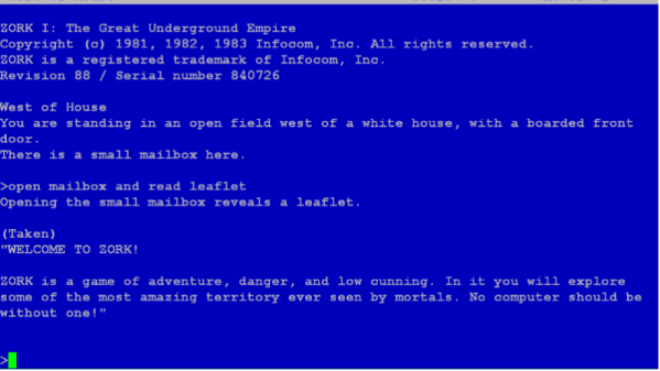
The Z-machine created by [Dan], which he’s calling A2Z, allows users to run Zork and other compatible interactive text games on the ItsyBitsy without any additional hardware. Just plug the board into your computer and you’ll be able to play the games over the the serial connection. He’s even implemented some retro color schemes to make the experience more authentic, like the blue of the Amiga or Compaq green.

We’ve covered previous projects that brought Zork and friends to the Arduino, your web browser via a virtual Altair 8800, and even some more exotic targets like custom FPGAs. You can play cave adventure, the game that inspired Zork, on the Supercon Badge.

Printed Parts Turn Ruler Into Marking Gauge

For Hackaday readers who spend more time with a soldering iron than a saw, a marking gauge is a tool used to put parallel lines on a piece of wood (and occasionally metal or plastic) for cutting. The tool is run across the edge of the piece to be marked, and an adjustment allows the user to set how far in the line will be made. As an example, if you wanted to cut a board into smaller strips, a marking gauge would be an ideal choice for laying out your lines ahead of time.

But as with many niche tools, it’s not something you’re going to use every day. For [chaosbc], this meant he wanted to see if he could come up with a DIY solution on the cheap. Plus he could have it in hand now, rather than waiting for it to take the slow boat from overseas. With the addition of a few clever 3D printed components, he was able to turn his trusty aluminum ruler into a serviceable marking gauge for the cost of filament and a few bits of hardware.

The general design of a marking gauge is fairly simple: there’s a block that rides up and down a graduated shaft (known as the headstock) which allows you to set the depth of the line, and then a piece on the end which holds your marking tool. The marking tool could be a blade if you’re working with something soft enough, but for wood is usually going to be a pencil.

[chaosbc] provides all the STL files for his DIY marking gauge, though they might need adapting as they were created for his specific ruler. Luckily the parts aren’t that complex so it shouldn’t be too difficult to get it sorted out. He also has a useful hint for anyone looking to duplicate his work: a few drops of super glue on the bolt used to lock down the headstock is enough to create a non-marring surface so you don’t tear up your ruler.

We’ve got a few other tips for woodworking on a budget, as well as a primer about this whole making stuff with dead trees concept.

Continue reading “Printed Parts Turn Ruler Into Marking Gauge”

Teardown Of A (Relatively) Cheap Thermal Camera

The cost of tools and test equipment has largely been on the downward trend for years, making it now more affordable than ever to get into the hacking and making scene. This is particularly visible with something like the venerable oscilloscope: a piece of equipment that was near unobtainium for the home hacker a decade ago, you can now get digital pocket scope for as little as $20 USD. But there are still pieces of gear which haven’t quite hit the sort of prices we’d like to see.

A perfect example are thermal imaging cameras. The cheap ones are usually so low resolution they might as well just be thermometers, but the higher resolution ones can cost thousands. [Rob Scott] recently wrote in to tell us about a very promising middle ground, the HTI HT-A1. But he didn’t just point it out to us, he also tore it down and laid its internal’s bare for our entertainment. Now that’s our kind of introduction.

[Rob] walks us through the disassembly of the device, which is made unnecessarily difficult due to the fact that half the screws are hidden under a glued on screen bezel. That means a heat gun, a thin tool, and patience are in order if you want to get inside the device. It’s bad enough they use these kinds of construction techniques on modern smartphones, but at least they’re so thin that we can understand the reasoning. Why this chunky thing needs to resort to such measures is beyond us.

Eventually he cracks the HT-A1 open and is greeted with a single double-sided PCB. The top side is pretty much bare except for the buttons and the LCD display, and the flip side is largely just a breakout for a quad-core Allwinner A33 daughterboard. [Rob] theorizes this is to keep costs down by allowing reuse of the modular A33 board on other devices. Given the A33’s use in so many cheap tablets, it’s also possible HTI simply purchased these daughterboards as a drop-in component and designed their own board around it.

There’s not much else inside the HT-A1 beyond the rechargeable battery pack and thermal camera, both attached to the device’s rear panel. [Rob] noticed that the date on the thermal camera PCB is a full two years older than the date on the main PCB, leading one to wonder if HTI might have gotten a good deal on a bunch of these slightly outdated sensors and spun up a whole device around them.

The HT-A1 is high enough resolution that you can actually pick out individual components on a PCB, and at $400 USD is approaching a reasonable price point for the individual hacker. Which is not to say it’s cheap, but at least you get a useful tool for your money. We wouldn’t suggest you buy this device on a whim, but if you do a lot of diagnostic work, it might pay for itself after a couple repairs.

If that’s still a little too rich for your blood, we’ve covered a handful of DIY options which might better fit your budget.

Continue reading “Teardown Of A (Relatively) Cheap Thermal Camera”

Rooting The Amazon Fire TV Cube With An Arduino

Amazon might not be happy about it, but at least part of the success of their Fire TV Stick was due to the large hacking and modification scene that cropped up around the Android-powered device. A quick search on YouTube for “Fire Stick Hack” will bring up a seemingly endless array of videos, some with millions of views, which will show viewers how to install unofficial software on the little media dongle. Now it looks like their latest media device, the Fire TV Cube, is starting to attract the same kind of attention.

The team at [Exploitee.rs] has recently taken the wraps off their research which shows the new Fire TV Cube can be rooted with nothing more than an Arduino and an HDMI cable you’re willing to cut apart. Of course, it’s a bit more complicated than just that, but between the video they’ve provided and their WiKi, it looks like all the information is out there for anyone who wants to crack open their own Cube. Just don’t be surprised if it puts you on the Amazon Naughty List.

The process starts by putting the device’s Amlogic S905Z into Device Firmware Upgrade (DFU) mode, which is done by sending the string “boot@USB” to the board over the HDMI port’s I2C interface. That’s where the HDMI cable comes in: you can cut into one and wire it right up to your Arduino and run the sketch [Exploitee.rs] has provided to send the appropriate command. Of course, if you want to get fancy, you could use an HDMI breakout board instead.

With the board in DFU mode in you gain read and write access to the device’s eMMC flash, but that doesn’t exactly get you in because there’s still secure boot to contend with. But as these things tend to go, the team was able to identify a second exploit which could be used in conjunction with DFU mode to trick the device into disabling signature verification. Now with the ability to run unsigned code on the Fire TV Cube, [Exploitee.rs] implemented fastboot to make it easier to flash their custom rooted firmware images to the hardware.

As with the Fire TV Stick before it, make sure you understand the risks involved when you switch off a device’s security features. They’re often there to protect the end user as much as the manufacturer.

Continue reading “Rooting The Amazon Fire TV Cube With An Arduino”

Pocket Sized Arduino Calculator Makes A Great First Project

We’ve all got calculators on our phones, in our web browsers, and even in the home “assistant” that’s listening in on your conversations all day on the off chance you blurt out a math question is can solve for you. The most hardcore among us might even still have a real calculator kicking around. So in that light, building your own DIY calculator might not seem too exciting. But we can’t deny this Arduino calculator project by [Danko Bertović] would look good sitting on the bench.

In the video after the break, [Danko] walks us through the creation of the calculator, from placing all the through-hole components to writing the code that pulls it all together. Special attention is given to explaining the wiring, making this is a good project for those just getting started on their digital hacking journey. It also helps that the whole thing is put together on perfboard with jumper wires; no PCB fabrication required for this one.

For the user interface, [Danko] is using an array of 17 tactile switches for the keyboard and a very crisp 128×32 I2C OLED display. Beyond the battery, a crystal, and a handful of passive components, that’s about all the support hardware it takes to put this project together. You don’t even need an enclosure: a second piece of perfboard and some standoffs are used to sandwich the battery and fragile wiring inside.

Of course, the star of the show is the ATmega328P microcontroller, which is mounted in a place of honor right under the OLED screen. The chip gets programmed in an Arduino Uno and then transplanted into the calculator, a neat trick if you don’t have a dedicated programmer handy. Given how cheap Arduino clones can be had online, this is becoming a more common practice.

The construction of this calculator reminds us a bit of the DIY Sinclair scientific calculator we looked at over the summer. But if you want to see the peak of homebrew calculator technology, this Raspberry Pi powered build is tough to beat.

Continue reading “Pocket Sized Arduino Calculator Makes A Great First Project”

An OpenSCAD Mini-ITX Computer Case

We’re no strangers to 3D printed enclosures here at Hackaday. From the plethora of printed Raspberry Pi cases out there to custom enclosures for electronic projects, small plastic boxes turn out to be an excellent application for desktop 3D printing. But as printers get bigger and filament gets cheaper, those little boxes don’t always need to be so little. We aren’t talking about running off boxes for your sneaker collection either, if you’ve got the time and the print volume, you could whip up an enclosure for your PC.

[Nirav Patel] writes in to share his impressive 3D printed Mini-ITX computer case project, which would be a neat enough trick in its own right, but he took the concept one step farther and made it a parametric design in OpenSCAD. This allows the user to input their particular hardware configuration and receive STL files for a bespoke case. The list of supported hardware isn’t that long yet, but with the OpenSCAD code up on GitHub and released under the BSD license, hopefully the community can improve on that as time goes on.

To keep things simple (and strong), [Nirav] implemented what he refers to as a “bucket” design. The majority of the case is a single print, which does take a long time (just shy of 40 hours on his Prusa i3 MK3), but nearly eliminates any post-printing assembly. Only the optional feet and the lid need to be printed separately. Threaded inserts are used throughout the design for mounting hardware, so you don’t run the risk of blowing out the printed holes during hardware changes or upgrades.

A particularly neat feature, and a testament to the power of OpenSCAD, is the fact that the case’s internal volume is calculated and embossed into the side of the design. Does this have any practical purpose? Not exactly, but [Nirav] thought it would be appealing to the Mini-ITX case modding community which apparently measures their accomplishments in liters of volume.

We’ve seen a 3D printed computer case before, but it used acrylic sheets and couldn’t be made without a large format printer. There’s something to be said for a project that can be completed on the hacker community’s favorite printer.

ESP8266 Monitor Keeps An Eye On OctoPrint

At this point, you’ve almost certainly heard of OctoPrint. The web-based control interface for 3D printers is especially popular for those who’s primary computers run on an operating system that has a penchant for occasionally imploding. Even if you aren’t laboring under that common software handicap, OctoPrint offers a wide away of compelling features. Perhaps chief among them the ability to monitor your printer over the network, and if you insist, over the Internet. But while OctoPrint provides the server side for getting your printer on the net, you’re on your own for the client.

Rather than using a web browser like some kind of peon, [David Payne] has come up with a very slick desktop OctoPrint monitor using the WeMos D1 Mini ESP8266 board. With an exceptionally low part count and housed in a (what else) 3D printed enclosure, this is a cheap and easy OctoPrint accessory that we suspect will be decorating many a hacker’s desk before too long.

The electronics are simple to the extreme, just hook the 4 wires of an 128×64 OLED I2C display to the appropriate pins of the ESP8266 board, and you’re ready to upload the Arduino code [David] has come up with.

His code is very polished, from using WiFiManager for initial network setup to providing its own web-based configuration menus to get the device linked up to your OctoPrint instance, [David] clearly wanted this to be as smooth an experience as possible for the end user. When the 3D printer isn’t working on a job, the monitor will even switch over to showing you the time and weather. We’ve seen commercial products that weren’t this user-friendly.

We also love the case design on this little gadget. While the aesthetics are perhaps debatable (sort of reminds us of the little fellows from Darwinia), we appreciate any functional print that doesn’t require supports. You’ll need to provide a couple of little screws to keep the back panel on, but other than that everything snaps into place.

Of course, you could always just use your smartphone to keep an eye on OctoPrint, and even if the remote management capabilities don’t grab your interest, there’s plenty of interesting plugins to keep you occupied.

Continue reading “ESP8266 Monitor Keeps An Eye On OctoPrint”