Held Captive By Arduino And Multiple RFID Readers

If you’re the kind of person who has friends, and/or leaves the confines of the basement from time to time, we hear that these “Escape Rooms” are all the rage. Basically you get locked into a room with a couple other people and have to solve various problems and puzzles until you’ve finally made enough progress that they let you out. Which actually sounds a lot like the working conditions here at Hackaday HQ, except they occasionally slip some pizza rolls under the door for us which is nice.

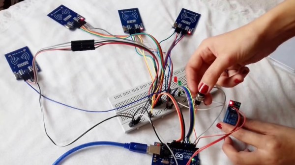
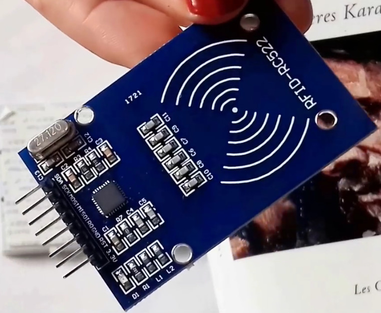
Whichever side you find yourself on in one of these lighthearted hostage situations, knowledge of this multi-tag RFID lock created by [Annaane] may come in handy. By connecting multiple MFRC522 RFID readers to an Arduino Uno, she’s come up with a method of triggering a device (like an electronic door lock) only when the appropriate combination of RFID tags have been arranged. With a little imagination, this allows for some very complex puzzle scenarios which are sure to keep your prisoners enthralled until you can lower the lotion down to them.

Her code allows you to configure the type and number of RFID cards required to trigger one of the Arduino’s digital pins, which usually would be connected to a relay to fire off whatever device you want. The Arduino sketch is also setup to give “hints” to the player by way of a status LED: fast blinking let’s you know the tag scanned is wrong, and slow blinking means you don’t have enough scanned in yet.

The video after the break shows some highlights of the build, as well as a quick demonstration of how both the RFID “combination” and manual override can be used to trigger the attached relay.

Hackers do love RFID. Using them for physical access control is a fairly common project around these parts, and we’ve even seen similar setups for the digital realm.

Continue reading “Held Captive By Arduino And Multiple RFID Readers”

VCF East XIII Is Right Around The Corner

The middle of May is a very special time at the Jersey Shore. It’s finally warm enough that business owners decide they might as well unlock their doors, but still cool enough that you can go on the boardwalk without having to bump into sweaty strangers. It’s a time for saltwater taffy without the risk of skin cancer, for hot dogs without seagulls trying to steal them from you. You get the idea.

This year it’s also when the Vintage Computer Festival East will be held in Wall, New Jersey. Running from May 18th to the 20th, VCF East XIII will play host to talks, workshops, and demonstrations focusing on the storied days before we all started carrying supercomputers in our pants. Of course it wouldn’t be a computer festival without vendor tables, and there’s even a consignment area where VCF staffers will sell your old gear while you peruse the show.

Here’s hoping that [Don Eyles] brings his hardcopy of the lunar module source code with him. Our own [Greg Charvat] got a close look at this incredible piece of history.
A trio of keynote speakers will help set the tone of VCF East. On Friday [Bill Dromgoole] will discuss the ongoing restoration of a UNIVAC 1219-B military mainframe. Once designed to handle the radar on a Navy destroyer, thanks to the tireless efforts of [Bill] and his merry band, it’s currently on the hunt for the Wumpus. Saturday will see NASA contractor [Don Eyles] explain how he hacked his way around a stuck “Abort” button on Apollo 14, deftly avoiding the kind of problems the previous guys had in getting to the Moon. Finally on Sunday [Dave Walden] will talk about his work in Ye Olden Days of the Internet: programming the very first routers, known as “Internet Message Processors” or IMPs.

If you’re looking to get up close and personal with tech of yesteryear, you’ll definitely want to check out the exhibit area. Arguably the largest single draw of VCF, this is where you’ll see everything from 1980’s robots to software defined radio on the MITS Altair 8800. In previous years we’ve seen WWII Enigma machines, as well all the cool toys that kids had back in the day.

As usual we’ll be there to take plenty of pictures and dive into the sundry amusements offered by the show and the InfoAge Museum which plays host to it. Hackaday is once again a proud sponsor of VCF East and their continuing efforts to preserve technology history for future generations. We’d love to see you there and we’re always looking for the inside scoop on interesting hardware so don’t be shy about tracking me down with your story!

1960’s Console Stereo Gets Raspberry Pi Touch Screen

When he was but a wee hacker, [WhiskeyDrinker] loved to play with the big console stereo his grandparents had. The idea of a functional piece of furniture always appealed to him, and he decided that when he grew up and had a place of his own he’d get a similar stereo. Fast forward to the present, and a Craigslist ad for a working Penncrest stereo seemed to be a dream come true. Until it wasn’t.

The original physical controls are connected to the Pi’s GPIO

As difficult as it might be to believe, sometimes things we read on the Internet are not true. The “working” Penncrest radio turned out to be a dud. But realizing that the look of the cabinet was more important to him than historical accuracy, [WhiskeyDrinker] decided to outfit it with a Raspberry Pi powered touch screen that would look as close to stock hardware as possible.

The final result really does look like some kind of alternate timeline piece of consumer electronics: where chunky physical buttons and touch screens coexisted in perfect harmony. The vintage stereo aficionados will probably cry foul, but let them. [WhiskeyDrinker] did a fantastic job of blending old and new, being respectful to the original hardware and aesthetic where it made sense, and clearing house where only nostalgia had lease.

A HiFiBerry DAC+ Pro is used to get some decent audio out of the Raspberry Pi, and the touch screen interface is provided by Volumio. [WhiskeyDrinker] mentions that it even has a GPIO plugin which he successfully used to handle getting the physical buttons to play nice with their digital counterparts.

Updating old audio gear is always a sensitive subject around these parts. Sometimes they go so far that the original hardware is almost an afterthought. On the other side of the spectrum are the projects which try to take modern gear and mimic the look of the classics. In any event, one thing is clear: they don’t make ’em like they used to.

Continue reading “1960’s Console Stereo Gets Raspberry Pi Touch Screen”

Push It To The Limit: SSD1306 At 150 FPS

A good deal of the projects we cover here at Hackaday are not, in the strictest sense, practical endeavors. If we required that everything which graced our digital pages had a clear end result, the site would be in a rather sad state of affairs. Sometimes it’s enough just to do something for the challenge of it. But more often than not, you’ll learn something in the process which you can use down the line.

That’s precisely what pushed [Larry Bank] to see how well he could optimize the frame rate on the popular SSD1306 OLED display. After several iterations of his code, he was able to achieve a blistering 151.5 FPS, with apparently still some room for improvement if he’s feeling up to the challenge. But considering his first attempt was only running at 5.5 FPS, we’d say he’s already more than earned his hacker cred on this one.

A few different tricks were used to achieve such incredible performance gains. To start with, while the official I2C specification says you’re supposed to wait for an acknowledgment back from the device when communicating with it, [Larry] realized the SSD1306 didn’t actually care. He could continuously blast commands at the display without bothering to wait for an acknowledgment. He admits there are problems with this method, but you can’t argue with the results.

To really wring all the performance out of the system he could, [Larry] donned his Assembly Cap and examined how the Arduino IDE compiler was interpreting his code. He identified a few areas where changing his C code would force the compiler to generate faster output. He notes that this wouldn’t normally be required when working with more advanced compilers, but that the Arduino toolchain needs its hand held occasionally.

This isn’t the first time we’ve seen somebody try and push more pixels through the very same OLED display, and it’s interesting to see the two very different approaches to the same goal.

Putting The Mooshimeter To Sleep With A Bit Of Mercury

If you haven’t heard of it, the Mooshimeter is a two channel multimeter that uses your smartphone as a display over Bluetooth 4.0. The ability to simultaneously monitor voltage and current is rather unique, and the fact that you aren’t physically tethered to the thing makes it ideal for use in hard to reach or even dangerous locations. The promotional material for the Mooshimeter shows users doing things like leaving the device inside the engine compartment of a car while they drive around and take readings about the vehicle’s electrical system.

Note the vertical orientation

All that sounds well and good, but at the end of the day, the Mooshimeter is probably not going to be your primary multimeter. It’s going to stay on a shelf until a task befitting its unique abilities comes along. Unfortunately, as [nop head] found, that can be a problem. Like many modern devices, the Mooshimeter doesn’t actually turn off. It just sits there draining its battery until you’re ready to use it. Which of course means that when you’re finally ready to pull the thing out and put it to use, you get a low battery warning and need to put new AAs in it. First World problems.

The fix for this thoroughly modern problem is delightfully old school: a mercury tilt switch.

Using a small spacer made of Kapton tape, [nop head] was able to isolate the battery contacts from the PCB itself. He then soldered the mercury switch in place between them, making sure to position the bulb vertically. When the Mooshimeter is right side up, the mercury flows down and bridges the contacts; but when the device is inverted the contact is broken and the batteries stop draining. He still has to remember to put the Mooshimeter face down when he’s done with it, but it’s better than dealing with constant dead batteries.

There was a lot of initial interest in the Mooshimeter when it was announced in 2014, but we’ve seen precious little of it since. It certainly seems neat, but perhaps it’s a bit too niche for its own good? If Mooshimeter fulfills a critical role in your tool set, let us know in the comments below.

Waking Up To Classic Soundgarden Screaming

In a project that was really only slighly less creepy before the singer’s untimely death in 2017, this alarm clock built by [Rafael Mizrahi] awakens its user to a random selection of Chris Cornell’s signature screams. Not content to be limited to just the audio component of the experience, he contained all of the hardware within a styrofoam head complete with a printed out facsimile of the singer’s face.

An Arduino Uno coupled with a seven segment LED display provides the clock itself, which is located in the base. There’s no RTC module, so the Arduino is doing its best to keep time by counting milliseconds. This means the clock will drift around quite a bit, but given that there’s also no provision for setting the time or changing when the alarm goes off short of editing the source code, it seems like accurate timekeeping was not hugely important for this project.

Audio is provided by an Adafruit VS1053, which contains a microSD card full of MP3 samples of Cornell’s singing. This is connected to an X-Mini portable capsule speaker which has been installed in a hollowed out section of the foam.

Unconventional alarm clocks are something of a staple here at Hackaday. From ones which physically assault you to mimicking sunrise with OLEDs, we thought we had seen it all. We were wrong.

Continue reading “Waking Up To Classic Soundgarden Screaming”

Flash And Debug ESP8266 Boards On Android

Have an ESP8266 development board such as the NodeMCU or Wemos D1? You’re currently reading Hackaday, so probably. Got an Android device kicking around? Also seems fairly likely. In that case, you should check out ESP8266 Loader by [Bluino Electronics]. This recently released application lets you not only flash new binaries to any ESP8266 board using the FTDI, PL2303, CH34X and CP210X USB chipsets, but also offers a serial monitor for debugging on the go.

You’ll need a USB OTG cable to get your ESP board jacked in to your Android device, but you don’t need root or even to fiddle with the development settings. Here at the Hackaday R&D Dungeon we had somewhat mixed success getting a random selection of Android devices to work fully; all of the ones tried could at least open the serial monitor and read what a pre-programmed ESP was saying, but not all of them could successfully program a board.

Even on the devices where programming worked, it was slow. Just a basic LED blinking Sketch took long enough to write to our test Wemos D1 Mini that we contemplated getting a snack. But still, it shows a lot of promise for managing devices in the field, especially if you don’t have over the air update enabled in your code.

We especially liked that ESP8266 Loader helpfully downloaded a bunch of example binaries, many of which could be of practical use. There are programs for toggling the different GPIO pins on the board, creating Wi-Fi access points, and even a basic web server. With these in hand, you could actually do some testing and diagnostic work right from your mobile device.

This isn’t the first time we’ve seen an ESP8266 team up with a mobile device, but generally speaking, the magic is done over WiFi or Bluetooth.