Impedance Matching Revisited

If you are an old hand at RF design, you probably have a good handle on matching impedance. However, if you are just getting started with RF, [FesZ Electronic]’s latest video series on lossless impedance matching is well worth watching.

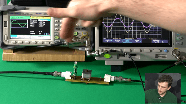
Matching is important for several reasons. Maximum power transfer occurs when the source and load impedance match. Also, at RF, mismatched impedance can cause reflections which, again, robs you of useful power. The video covers some math and then moves on to LTSpice to simulate a test circuit. But the part you are really waiting for — the practical circuits — is about 15 minutes in. Since the values you need are often oddball, [FesZ] makes his own adjustable inductors and uses a trimmer capacitor to adjust the actual capacitance value.

This is a big topic, but the first video is a great introduction blending theory, simulation, and hands-on. A great way to get started with a very fundamental RF design skill.

We’ve worked on explaining all this before if you want a second take on it. If you want to understand why mismatched impedance leads to less power delivery, we’ve done that, too.

Continue reading “Impedance Matching Revisited”

Art of 3D printer in the middle of printing a Hackaday Jolly Wrencher logo

3D Printering: Soldering A Heated Bed

There’s an old saying about something being a “drop in the ocean.” That’s how I felt faced with the prospect of replacing a 12 V heated bed on my printer with a new 24 V one. The old bed had a nice connector assembled from the factory, although I had replaced the cable long ago due to heating issues with that particular printer. The new bed, however, just had bare copper pads.

I’m no soldering novice: I made my first solder joint sometime in the early 1970s. So I felt up to the challenge, but I also knew I wouldn’t be able to use my usual Edsyn iron for a job like this. Since the heated bed is essentially a giant heatsink for these pads, I knew it would require the big guns. I dug out my old — and I mean super old — Weller 140 W soldering gun. Surely, that would do the trick, right?

Continue reading “3D Printering: Soldering A Heated Bed”

LED Bubbles From The 1970s Tell The Time

[CuriousMarc] is nothing if not curious. Finding some old TI timekeeping chips to reverse engineer, he set out to make a clock using old-fashioned “bubble LEDs.” You can see the result of his tinkering in the video below. For the uninitiated, bubble LEDs are 7-segment LEDs with magnifying bubbles over each digit. These were popular in calculators, watches, and other places that used LEDs before LCDs largely displaced them.

The history of these has to do with the power required to light an LED. You don’t technically need a magnifying lens, but larger LEDs take more power. These displays were relatively low power and used tiny LEDs with light pipes to make each dot a full segment. The lens made the segments larger and easier to see.

Beyond the TI chip and HP displays, there isn’t too much else needed. [Marc] just wired the whole thing using the IC as a substrate. Sort of dead bug construction using enameled wire. At first, it didn’t work but it turned out to be a battery issue. The device really wanted 2.5 V and not the 3 V provided by the battery. The solution required a little detective work.

We know this isn’t a very practical project, but we love seeing this old tech again and while the dead bug construction isn’t beautiful, there is something appealing about the look of it. Maybe one day people will build steampunk things and discopunk will be for the 1970s?

We’ve seen bubble LED projects before. If you want something more in a watch form factor, that exists, too.

Continue reading “LED Bubbles From The 1970s Tell The Time”

This John Deere Tractor Doesn’t Need A Driver

While most autonomous vehicles are meant to travel over the highway, John Deere’s new 8R tractor shown at the 2022 Consumer Electronics Show will likely only traverse fields and it will do so without a human at the wheel.

The tractor is slated to be available to farmers in late 2022 and has six pairs of stereo cameras to generate a 360 degree view of obstacles. It also uses location technology, including GPS, to ensure it is where it is supposed to be with a claimed accuracy of 1 inch. You can see a video about the beast below.

Continue reading “This John Deere Tractor Doesn’t Need A Driver”

Modernizing The Game Boy Advance

[Zekfoo] decided to honor the Game Boy Advance’s 20th birthday by redesigning it at the circuit level to give it a more modern twist. To quote the project readme:

I really want to like the Game Boy Advance. Growing up with a GBA SP, I was spoiled by its clicky buttons, rechargeable battery, and illuminated screen. When I finally got my hands on an original GBA, I couldn’t be more disappointed by the stark difference in feel and function. While today’s retro modding scene has produced many improvements for the GBA (referred to from now on as its codename AGB), the console still has many quirks that simple modding hasn’t been able to fix, but that can be addressed in a circuit redesign.

The four-layer board looks great and there a number of modernized features.

For example, this new version is rechargeable. The unit has proper switches, which most people will prefer over the mushy membrane switches. There’s also a screen light and an improved power supply that helps produce cleaner audio, among other things.

We were disappointed that the repository only has images and audio files — if you want to duplicate the build you are on your own. He’s also done a clone of the Game Boy Color, but — alas — no design files there either. Still, a couple of good-looking projects.

We always enjoy seeing old products given a facelift. If you think you just need an emulator, they sometimes don’t exactly mimic real hardware.

How Many Wires Do You Need To Measure A Resistor?

Measuring resistance doesn’t seem to be a big deal. Put your meter leads across two wires or terminals and read the value, right? Most of the time that is good enough, but sometimes you need better methods and for those, you need more wires, as [FesZ] explains in his recent video that you can see below.

In the usual case, the meter applies a known voltage and measures the current which, by Ohm’s law, gives you the resistance. It is also possible to control the current and measure the voltage — doesn’t matter. [FesZ] shows how many meters measure voltage across a known resistor and the unknown so that a precision voltage or current source isn’t necessary.

But there are a number of problems with this simple method. For one thing, the test leads have resistance as well. So some voltage will drop across them, contributing to measurement error. Sure, that extra 0.5 ohms won’t matter if you are looking at a 100K resistor, but if you are trying to measure, say, the heated bed of a 3D printer, that extra 0.5 ohms is a large percentage of the total measurement.

Bench meters for lab use often support 4-wire measurements. As [FesZ] shows, this method measures three different voltages to try to negate some of the measurement errors. We liked that he used three different meters to show how it works and the difference between a 2-wire and 4-wire measurement on a small resistor.

There’s an even stranger method using 3 wires to save on wiring for, say, a sensor a long distance away. There are actually at least two ways to use 3 wires, and the video covers both of them.

For measuring resistors in a circuit, though, you need a whopping six wires. This technique uses the two extra wires to control a balance voltage that keeps the current between the unknown resistor and the rest of the circuit at zero. This prevents current flowing except for the measurement current. You’ll see a simulation of how this works in the video.

We’ve looked at 4-wire measurements before if you want some practice simulations to try. Probes for this measurement are a popular project, too.

Continue reading “How Many Wires Do You Need To Measure A Resistor?”

How Do Capacitors Work?

If you are like [The Science Asylum], you might wonder how a capacitor can work since, at their core, they are nothing more than a gap filled with air or another insulator. He explains how in a recent video you can see below.

Of course, at DC, a capacitor doesn’t conduct any better than the insulator used as its dielectric. However, a DC voltage has to start sometime and when it does, it briefly looks like AC. The video explains it all in simple terms. Of course, if you are math savvy, you can probably get as much out of the normal C=dQ/dV equation.

If that doesn’t speak to you, the explanation in the video about charges will shed some light. He even shows an animation of the classic “hydraulic model”, which is helpful to develop intuition about the process.

Continue reading “How Do Capacitors Work?”