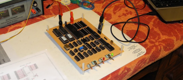
[Jeff Tranter] has done a number of retrocomputing projects. But he wanted to tackle something more substantial. So he set out to build a 68000-based single board computer called the TS2 that he found in a textbook. He’s documented it in a series of blog posts (about 30 posts, by our count) and a video that you can see below.
The 68000 had a very rational architecture for its day. A flat memory space was refreshing compared to other similar processors, and the asynchronous bus made hardware design easier, too. While most CPUs of the era assumed bus devices could perform their service in a fixed amount of time, the 68000 used a handshake with devices to allow them to take the time they needed. Most other CPUs had to provide a mechanism for a slow device to stall the bus which was complicated and, in many cases, less efficient.
We often wonder how many people have 3D printers and wind up just printing trinkets off Thingiverse. To get the most out of a printer, you really need to be able to use a CAD package and make your own design. However, just like a schematic editor doesn’t make your electronic designs work, a CAD program won’t ensure you have a successful mechanical part.
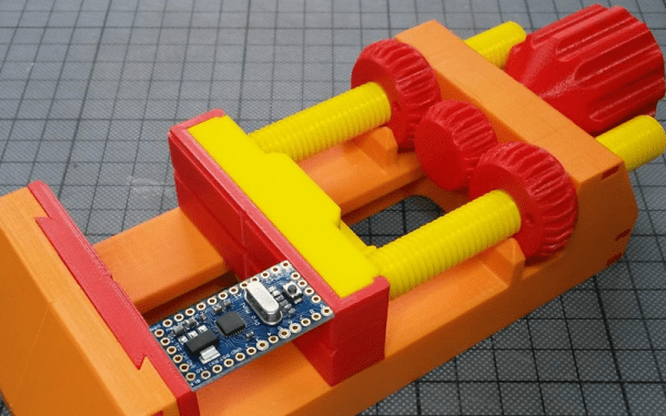
[TheGoofy] has a 100% 3D printed vise that looks like it is useful. What’s really interesting, though, is the video (see below) where he explains how printing affects material strength and other design considerations that went into the vise.
We don’t know if [OH8STN] has a military background, but we suspect he might since his recent post is about a “DIY Man Portable Magnetic Loop Antenna.” “Man-portable” is usually a military designation, and — we presume — he wouldn’t object to a woman transporting it either.
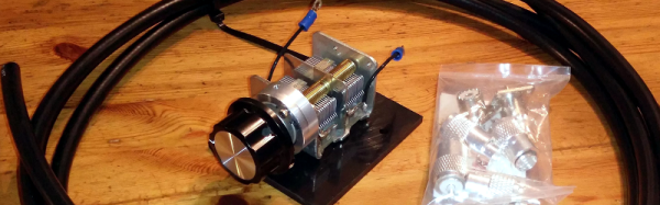
[OH8STN] started with a Chameleon antenna starter kit. This costs about $100 and is primarily a suitable variable capacitor with a 6:1 reduction drive premounted and soldered. Of course, you could source your own, but finding variable capacitors that can handle transmit duty (admittedly, these can apparently handle about 10 W continuous or 25 W on single sideband) can be tricky, especially these days. Although he started with a kit, he did modify the antenna to switch between two different sets of ham radio bands. You can see the antenna in the video below.
Loop antennas aren’t ideal–but neither is any other small antenna. Because the loop is tightly tuned to a particular frequency, it requires retuning for even relatively small frequency changes, even though it can operate on many different frequencies. If you want more technical details, you might enjoy this recent presentation from [W4RAX]. The links at the end are worth checking out, too.
There is an old saying: “In theory, theory and practice are the same. In practice, they are not.” We spend our time drawing on paper or a computer screen, perfect wires, ideal resistors, and flawless waveforms. Alas, the real world is not so kind. Components have all kinds of nasty parasitic effects and no signal looks like it does in the pages of a text book.
Consider the following problem. You have a sine wave input coming in that varies between 0 V and 5 V. You want to convert it to a square wave that is high when the sine wave is over 2.5 V. Simple, right? You could use a CMOS logic gate or a comparator. In theory…
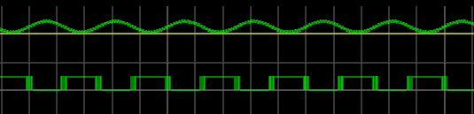
The problem is, the sine wave isn’t perfect. And the other components will have little issues. If you’ve ever tried this in real life, you’ll find that when the sine wave is right at the 2.5 V mark the output will probably swing back and forth before it settles down. This is exacerbated by any noise or stretching in the sine wave. You will wind up with something like this:
Notice how the edges of the square wave are a bit fat? That’s the output switching rapidly back and forth right at the comparator’s threshold.
Hysteresis
The answer is to not set the threshold at 2.5 V, or any other single value. Instead, impose a range outside of which it will switch, switching low when it leaves the low end of the range, and high when it exceeds the high end. That is, you want to introduce hysteresis. For example, if the 0 to 1 shift occurs at, say, 1.9 V and the 1 to 0 switch is at 0.5 V, you’ll get a clean signal because once a 0 to 1 transition happens at 1.9 V, it’ll take a lot of noise to flip it all the way back below 0.5 V.
You see the same effect in temperature controllers, for example. If you have a heater and a thermal probe, you can’t easily set a 100 degree set point by turning the heater off right away when you reach 100 and then back on again at 99.9999. You will usually use hysteresis in this case, too (if not something more sophisticated like a PID). You might turn the heater off at 99 degrees and back on again at 95 degrees, for example. Indeed, your thermostat at home is a prime example of a system with hysteresis — it has a dead-band of a few degrees so that it’s not constantly turning itself on and off.
Schmitt Triggers and How to Get One
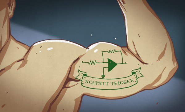
A Schmitt Trigger is basically a comparator with hysteresis. Instead of comparing the incoming voltage with VCC / 2, as a simple comparator would, it incorporates a dead band to ensure that logic-level transitions occur only once even in the presence of a noisy input signal.
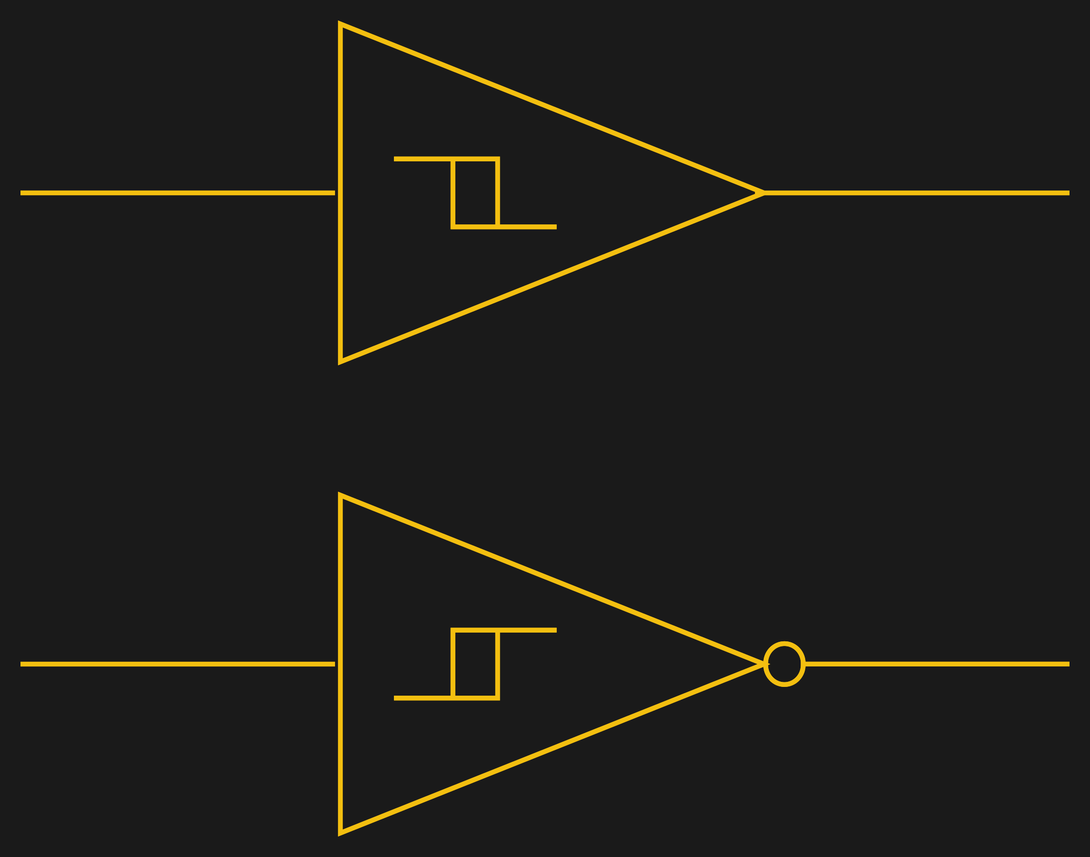
Assuming you want a Schmitt trigger in a circuit, you have plenty of options. There are ICs like the 74HC14 that include six (inverting) Schmitt triggers. On a schematic, each gate is represented by one of the symbols to the right; the little mark in the box is the hysteresis curve, and the little bubble on the output indicates logical negation when it’s an inverter.
You can also make them yourself out of transistors or even a 555 chip. But the easiest way by far is to introduce some feedback into a plain op amp comparator circuit.
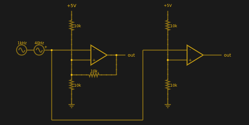
Below are two op amps, one with some positive feedback to make it act like a Schmitt trigger. The other is just a plain comparator. You can simulate the design online.
If you haven’t analyzed many op amp circuits, this is a good one to try. First, imagine an op amp has the following characteristics:
The inputs are totally open.
The output will do whatever it takes to make the inputs voltages the same, up to the power supply rails.
Neither of these are totally true (theory vs. practice, again), but they are close enough.
The comparator on the right doesn’t load the inputs at all, because the input pins are open circuit, and the output swings to either 0 V or 5 V to try, unsuccessfully, to make the inputs match. It can’t change the inputs because there is no feedback, but it does make a fine comparator. The voltage divider on the + pin provides a reference voltage. Anything under that voltage will swing the output one way. Over the voltage will swing it the other way. If the voltages are exactly the same? That’s one reason you need hysteresis.
The comparator’s voltage divider sets the + pin to 1/2 the supply voltage (2.5 V). Look at the Schmitt trigger (on top). If the output goes between 0 V and 5 V, then the voltage divider winds up with either the top or bottom resistor in parallel with the 10K feedback resistor. That is, the feedback resistor will either be connected to 5 V or ground.
Of course, two 10K resistors in parallel will effectively be 5K. So the voltage divider will be either 5000/15000 (1/3) or 10000/15000 (2/3) depending on the state of the output. Given the 5 V input to the divider, the threshold will be 5/3 V (1.67 V) or 10/3 V (3.33 V). You can, of course, alter the thresholds by changing the resistor values appropriately.
Practical Applications
Schmitt triggers are used in many applications where a noisy signal requires squaring up. Noisy sensors, like an IR sensor for example, can benefit from a Schmitt trigger. In addition, the defined output for all voltage ranges makes it handy when you are trying to “read” a capacitor being charged and discharged. You can use that principle to make a Schmitt trigger into an oscillator or use it to debounce switches.
If you want to see a practical project that uses a 555-based Schmitt, check out this light sensor. The Schmitt trigger is just one tool used to fight the imprecision of the real world and real components. Indeed, they’re nearly essential any time you want to directly convert an analog signal into a one-bit, on-off digital representation.
Building a crystal radio isn’t exactly rocket science. Some people who build them go for pushing them technically as far as they can go. Others, like [Billy Cheung], go for style points. The modular radio and phone speaker looks like it came out of the movie Brazil. The metallic gramophone-like speaker horn adds to the appeal and mechanically amplifies the sound, too.
The video (see below) isn’t exactly a how-to, but if you watch to the end there is enough information that you could probably reproduce something at least similar. There are actually several horns. One is made from copper, another from paper, and one from a plastic bottle.
[Robert Baruch] wanted to tackle a CPU project using an FPGA. One problem you always have is you can either mimic something that has tools and applications or you can go your own way and just build everything from scratch (which is much harder).
[Robert] took the mimic approach–sort of. He built a CPU with the express idea of running Infocom’s Z-machine virtual machine, which allows it to play Zork. So at least when you are done, you don’t have to explain to your non-tech friends that it only blinks an LED. Check out the video, below, for more details.
Well, honestly, [Michael Mayer’s] STM8 Arduino (called Sduino) isn’t actually much to do with the Arduino, except in spirit. The STM8 is an 8-bit processor. It is dirt cheap and has some special motor control features that are handy. There’s a significant library available for it. However, it can be a pain to use the library and set up the build.
Just like how the Arduino IDE provides libraries and a build system for gcc, Sduino provides similar libraries and a build system for the sdcc compiler that can target the STM8. However, if you are expecting the Arduino’s GUI or a complete knock off of the Arduino library, you won’t get that.