A modchip is a small PCB that mounts directly on a larger board, tapping into points on that board to make it do something it wasn’t meant to do. We’ve typically seen modchips used with gaming consoles of yore, bypassing DRM protections in a way that a software hacks couldn’t quite do. As software complexity and therefore attack surface increased on newer consoles, software hacks have taken the stage. However, on more integrated pieces of hardware, we’ll still want to return to the old methods – and that’s what this modchip-based hack of a Starlink terminal brings us.
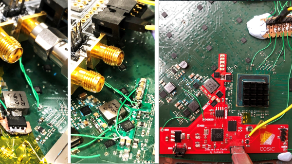
[Lennert Wouters]’ team has been poking and prodding at the Starlink User Terminal, trying to get root access, and needed to bypass the ARM Trusted Firmware boot-time integrity checks. The terminal’s PCB is satellite-dish-sized, so things like laser fault injection are hard to set up – hence, they went the voltage injection route. Much poking and prodding later, they developed a way to reliably glitch the CPU into verifying a faulty firmware, and got to a root shell – the journey described in a BlackHat talk embedded below. Continue reading “A Modchip To Root Starlink User Terminals Through Voltage Glitching”