A plastic steel drum toy

Odd Inputs And Peculiar Peripherals: Miniature Steel Drums Become Rotary Mouse Controllers

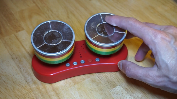
When [bornach] browsed through his office’s free-cycling box he found an old novelty toy that lets you play simple tunes on miniature steel drums. Such a thing is probably fun for about five minutes – if it’s working, which this one wasn’t. But instead of throwing it away, [bornach] spotted an opportunity in the capacitive touch pads on top of those little drums: they looked perfect to be modified into an unusual mouse cursor controller.

A steel drum toy being used to control a mouse cursorThe operation started with [bornach] ripping out the original PCB and replacing it with an ESP32 D1 Mini. That board has a handy stack of touch-sensitive pins which could interface directly with the drums’ touch pads. He then programmed the ESP32 to interpret the signals as mouse movements and button presses, and send the results to a computer through a BlueTooth connection.

Operating the mouse drums is so straightforward that they almost appear made for this purpose: you slide your finger in circles along the touch pads to move the cursor in the X or Y direction, and touch the center pad to click. The left drum moves the cursor horizontally while the right one moves it vertically, but there’s also a mode to use the right drum as a scroll wheel.

The rotary X/Y controls are reminiscent of an Etch-a-Sketch; while probably too clumsy for everyday use, they might come in handy in some circumstances where you need to make single-pixel-accurate motions, if only to click those miniscule “close” buttons on some online ads.

Amazingly, this isn’t the first Etch-a-Sketch style mouse we’ve featured: this cute little wooden device works in a similar way.

Continue reading “Odd Inputs And Peculiar Peripherals: Miniature Steel Drums Become Rotary Mouse Controllers”

A PCB carrying several Atari 2600 chips

Hackaday Prize 2022: The Baffatari 2600 Adds Atari Compatibility To Retrocomputers

Like today’s Intel-AMD duopoly, the market for home computer CPUs in the 1970s and ’80s was dominated by two players: Zilog with their Z80, and MOS Technology with their 6502 processor. But unlike today, even if two computers had the same CPU, it didn’t mean the two were software compatible: differences in memory layout, video interfaces, and storage media meant that software developed for an Atari 2600 wouldn’t run on an Apple I, despite the two sharing the same basic CPU architecture.

[Augusto Baffa]’s latest modern retrocomputer design, the Baffatari 2600, cleverly demonstrates that the difference between those two computers really is only skin-deep. The Baffatari is a plug-in board that adds Atari 2600 functionality to [Augusto]’s earlier Baffa-6502 system, which was designed to be Apple I-compatible. Since both the Apple and the Atari are powered by 6502 CPUs, only a few peripherals need to be swapped to change one into the other.

Sitting on the Baffatari board are two chips essential to the Atari 2600’s architecture: the 6532 RAM I/O Timer (RIOT) that contains the RAM and joystick interface, and the Television Interface Adapter (TIA) that handles the graphics and audio. These chips connect to the Baffa-6502’s system bus, enabling the main CPU to communicate with them and run Atari 2600 software titles. In the video embedded below, you can see several classic games running on the Baffa system.

The basic idea is similar to this RC2014 plug-in board that enables a Z80-based retrocomputer to run MSX and Colecovision titles. In fact, [Augusto] also built such a board for his earlier Z80 project.

Continue reading “Hackaday Prize 2022: The Baffatari 2600 Adds Atari Compatibility To Retrocomputers”

Bare-Metal STM32: Adding An Analog Touch With ADCs

An Analogue to Digital Converter (ADC) is at its core a straight-forward device: by measuring an analog voltage within a set range and converting the measured level to a digital value we can use this measurement value in our code. Through the use of embedded ADCs in microcontrollers we can address many essential use cases, ranging from measuring the setting on a potentiometer, to reading an analog output line on sensors, including the MCU’s internal temperature and voltage sensors.

The ADCs found in STM32 MCUs have a resolution between 12 to 16 bits, with the former being the most common type. An ADC can be configured to reduce this resolution, set a specific sampling speed, and set up a multi-mode configuration depending on the exact ADC peripheral. STM32 MCUs feature at least a single ADC peripheral, while some have multiple. In this article we will take a look at how to configure and use the basic features of the ADCs in STM32 MCUs, specifically the ADCs found in F0 and the ADC5_V1_1 type as found in most F3-family MCUs.

Continue reading “Bare-Metal STM32: Adding An Analog Touch With ADCs”

A GPS Frequency Standard For When The Timing Has To Be Right

A metrology geek will go to extreme lengths to ensure that their measurements are the best, their instruments the most accurate, and their calibration spot-on. There was a time when for time-and-frequency geeks this would have been a difficult job, but with the advent of GPS satellites overhead carrying super-accurate atomic clocks it’s surprisingly easy to be right on-frequency. [Land-boards] have a GPS 10 MHz clock that’s based around a set of modules.

Since many GPS modules have a 10 MHz output one might expect that this one to simply hook a socket to the module and have done, but instead it uses another of their projects, a fast edge pulse generator with the GPS output as its oscillator, as a buffer and signal conditioner. Add to that an QT Py microcontroller board to set up the GPS, and there you have a standalone 10 MHz source to rival any standard. Full details can be found on the project’s wiki, and the firmware can be found on GitHub.

Careful with your exploration of standard frequencies, for that can lead down a rabbit hole.

3D Printed Cartilage Ushers In Ear-a Of Custom Body Parts

When it comes to repairing human bodies, there’s one major difficulty: spare parts are hard to come by. It’s simply not possible to buy a knee joint or a new lung off the shelf.

At best, doctors and surgeons have made do with transplants from donors where possible. However, these are always in short supply, and come with a risk of rejection by the patient’s body.

If we could 3D print new custom body par/ts to suit the individual, it would solve a lot of problems. A new ear implant pioneered by 3DBio Therapeutics has achieved just that.

Continue reading “3D Printed Cartilage Ushers In Ear-a Of Custom Body Parts”

Reverse Engineering An Apollo-Era Module With X-Ray

The gear that helped us walk on the Moon nearly 60 years ago is still giving up its mysteries today, with some equipment from the Apollo era taking a little bit more effort to reverse engineer than others. A case in point is this radiographic reverse engineering of some Apollo test gear, pulled off by [Ken Shirriff] with help from his usual merry band of Apollo aficionados.

The item in question is a test set used for ground testing of the Up-Data Link, which received digital commands from mission controllers. Contrary to the highly integrated construction used in Apollo flight hardware, the test set, which was saved from a scrapyard, used more ad hoc construction, including cards populated by mysterious modules. The pluggable modules bear Motorola branding, and while they bear some resemblance to ICs, they’re clearly not.

[Ken] was able to do some preliminary reverse-engineering using methods we’ve seen him employ before, but ran into a dead end with his scope and meter without documentation. So the modules went under [John McMaster]’s X-ray beam for a peek inside. They discovered that the 13-pin modules are miniature analog circuits using cordwood construction, with common discrete passives stacked vertically between parallel PCBs. The module they imaged showed clear shadows of carbon composition resistors, metal-film capacitors, and some glass-body diodes. Different angles let [Ken] figure out the circuit, which appears to be part of a square wave to sine wave converter.

The bigger mystery here is why the original designer chose this method of construction. There must still be engineers out there who worked on stuff like this, so here’s hoping they chime in on this innovative method.

Shielding A Cheap RTL-SDR Stick

Even though not every Hackaday reader is likely to be a radio enthusiast, it’s a fair guess that many of you will have experimented with an RTL-SDR USB dongle by now. These super-cheap devices are intended for digital TV reception and contain an RTL2832 chip, which with the proper software, can be pushed into service as a general purpose software defined radio receiver. For around $10 USD they’re fantastic value and a lot of fun to play with, even if they’re not the best radio ever. How to improve the lackluster performance? One of the easiest and cheapest ways is simply to shield it from RF noise, which [Alan R] has done with something as mundane as a tubular fizzy orange tablet container.

This is probably one of the simpler hacks you’ll see on this site, as all it involves is making an appropriate hole in the end of the tube and shielding the whole with some aluminium foil sticky tape. But the benefits can be seen immediately in the form of reduced FM broadcast band interference, something that plagues the cheaper dongles.

Perhaps the value in this hack aside from how easy it is on a cheap dongle is that it serves to remind us some of the benefits of paying a little extra for a better quality device. If you’d like to know more about RTL-SDR improvements, it’s a topic we covered in detail back in 2019 when we looked at seven years of RTL-hackery.